
An Overly Sensitive One-Shot
This pulse stretcher circuit leverages the LT1720 comparator to create a reliable one-shot pulse generator with a remarkable response time. The sensitivity of the circuit allows it to detect low-voltage pulses, making it suitable for applications requiring precise timing control. The incorporation of the 1N5711 diode ensures that the circuit can handle fast switching operations without significant delay or distortion. The use of PSpice simulations validates the circuit's performance characteristics, confirming its ability to trigger accurately under specified conditions.
The notable challenge with this circuit lies in its recovery time, which can limit its effectiveness in high-frequency applications. The solution to this limitation involves integrating a FET switch, specifically the 2N7000, to discharge the timing capacitor (C7) quickly. This modification minimizes the recovery time significantly, allowing the circuit to reset and be ready for subsequent triggering events in a much shorter timeframe. The method for activating the FET at the appropriate moment is critical, as it directly influences the overall performance and reliability of the pulse generator.
The adjustments made to the biasing of the comparators enhance the overall stability of the circuit, ensuring consistent operation across varying input conditions. The increase in the input isolation resistor (R9) further aids in maintaining signal integrity, preventing unwanted interactions between the comparators and the timing capacitor. This careful design consideration is essential for achieving the desired performance in practical applications.
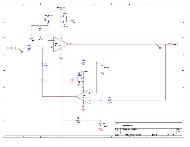
Overall, this pulse stretcher circuit exemplifies the principles of high-speed signal processing and pulse generation, providing a valuable tool for engineers in various electronic applications.This circuit is from the data sheet for Linear Technology`s LT1720 (a 4. 5ns comparator). It`s the circuit entitled "Pulse Stretcher" at the very end. Essentially, it`s a one-shot with sensitivity down to 14mV for 5ns to 10ns inputs (i. e. , it doesn`t require a full swing from logical low to high as do most one-shots), and TTL logic level outputs. I t also exhibits a mere 4. 5ns delay from input to output. Here`s an OrCAD schematic ( pdf ) used to simulate the circuit: The diode (D1) is a 1N5711. PSpice simulations indicate that it does indeed have the advertised sensitivity (I was able to get it to fire cleanly with a 5 ns 14mV pulse provided the input had 2ns rise and fall times). This is great. or so one would think. What the data sheet fails to mention is that this one-shot has a large recovery time (roughly 6 time constants), resulting in outputs of less than the desired time constant (1us for the above schematic) for any additional inputs arriving 1 to 7 time constants after the initial input.
Discharging the timing capacitor (C7) with a FET switch reduces the recovery time substantially. Here`s an OrCAD schematic illustrating how one might do this ( pdf ): The FET used is a 2N7000. If one could turn this FET on for about 15ns using the falling edge of the circuit`s output, the recovery time is reduced to no more than 20ns. In the above schematic this is done artificially by injecting the desired "on pulse" into the FET`s gate at the appropriate time.
Here`s a digital photo of a real version of the circuit: It doesn`t incorporate the FET switch (obviously), but otherwise follows the latter schematic. To improve the circuit`s stability I added a dc bias to the negative input of the lower comparator (U1), and increased the dc bias on the negative input of the upper comparator (U2) (which also made it necessary to increase the input isolation resistor, R9).
🔗 External reference
Related Circuits
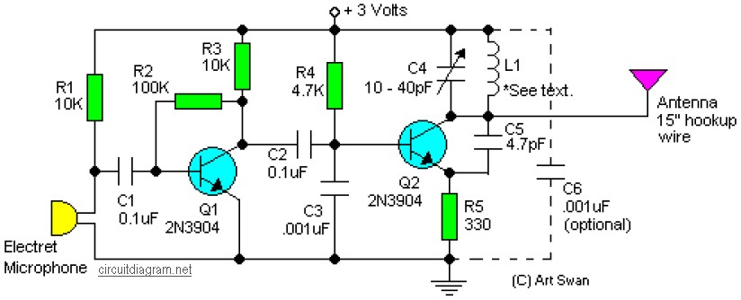
A simple and easy-to-build FM transmitter circuit that requires only two transistors. Typically, the default capacitor model is ceramic, preferably the NPO 1% type or an equivalent. However, almost any capacitor can be used in this circuit, but electrolytic...

The SLB0586A integrated circuit from Siemens can be utilized to construct a straightforward touch light dimmer circuit, enabling the adjustment of lamp intensity. When paired with a TIC206D triac, this setup allows for smooth regulation of light intensity for...
The TS555 is a single CMOS timer that provides low power consumption and high frequency, maintaining accurate timing in both monostable and astable modes. It produces reduced supply current spikes during output transitions, allowing for the use of smaller...
The most effective method for measuring current in a circuit is to insert a sense resistor into the current path. A higher resistance results in a more accurate measurement; however, it can also impact the circuit's operation. Utilizing an...

This sensitive FM radio tuner is an ideal circuit for hobbyists who wish to construct their own tuners rather than purchasing a pre-assembled product. The FM radio tuner circuit is designed to receive frequency modulation signals, providing a clear and...
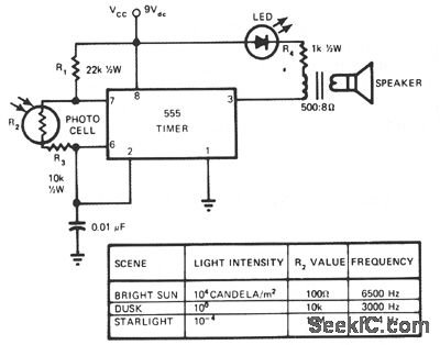
This circuit's frequency of oscillation increases directly with light intensity. The greater the light intensity, the higher the frequency of the oscillator. The 555 timer operates in astable oscillator mode, where frequency and duty cycle are controlled by two...