
Audio Preamplifiers Projects and Circuit
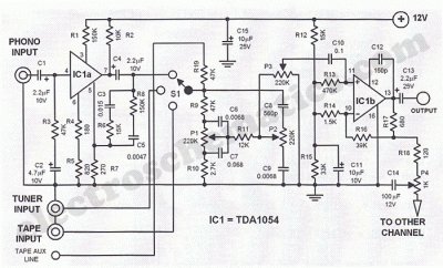
The TDA1054 integrated circuit is central to the operation of this Hi-Fi stereo preamplifier. With its dual preamplifier architecture, it allows for simultaneous amplification of stereo signals, which is essential for high-fidelity audio applications. The low noise characteristics of the TDA1054 contribute to the overall performance of the preamplifier, ensuring that audio signals are amplified without introducing significant noise or distortion.
The FET and PNP bipolar transistor combination enhances the circuit's performance by providing a high input impedance, which is critical for interfacing with various audio sources, including microphones. The low output impedance ensures compatibility with subsequent audio processing stages, such as mixers or amplifiers, thereby maintaining signal integrity throughout the audio path.
The SSM2015 microphone preamplifier is a notable feature of this design, as it is specifically engineered for low noise operation and high gain. Its ability to handle differential input signals makes it suitable for professional audio applications, where signal fidelity is paramount. The adjustable gain, determined by the resistors R4, R5, and R6, allows for flexibility in matching the preamplifier to different microphone types and input levels.
The scanning feature of the circuit, supported by the rectangular signal generator IC2c, adds a layer of functionality that enables automatic detection of active audio signals. This capability is particularly useful in live sound environments, where multiple microphones may be used, and the system needs to dynamically adjust to the presence or absence of sound.
Overall, this Hi-Fi stereo preamplifier circuit is a sophisticated design that combines various electronic components to achieve high-quality audio amplification with minimal noise, making it suitable for a wide range of professional audio applications.This Hi Fi stereo preamplifier circuit is built with TDA1054 IC from SGS. TDA1054 is a 16-pin DIL package and integrates 2 separate preamp circuits. It is a low noise preamp with little or no problem in the building process. The first half of the circuit (IC1a) it has an input sensitivity of 3 mV and has a frequency correction. Field Effect Transi stor is an amplifying device in which the output current depends on the input voltage. The FET Pre Amplifier described here is a sensitive and stable Preamp circuit using an N-Channel FET and a PNP Bipolar transistor. This combination gives high input impedance and low output impedance with stabilized gain. The microphone preamplifier circuit design presented in this schematic use SSM2015 produced by Precision Monolithics Inc.
(PMI) which offers a high amplification and low noise ( 1. 3nV/ f). Has been designed to work with differential input signals and can deliver 10 to 2000x amplification and it is term of R4 value. For R5 = R6. This mic preamp uses the low noise IC uA739. The circuit is an example of how a good preamplifier can be designed for dynamic microphones. The IC houses two identical integrated preamp circuits. The second preamp is used in identical manner for the second channel of the stereo microphone. Diagram bellow shows the pin numbers. A preamplifier circuit with a very low noise characteristic can be built by simply combining a FET transistor with a bipolar one.
The input impedance of the preamp circuit is almost the same as the gate impedance of the FET transistor (around 1M ©) The output impedance at the other end is about 1K ©. The frequency of. This circuit scan all the preamplifier entries to identify where is a audio signal and that entry remains selected.
After a sign of signal absence, scanning resumes. Scanning action is supported by rectangular signal generator IC2c. Scanner`s entries are connected to the audio entries from volume control board of the. 🔗 External reference
Related Circuits
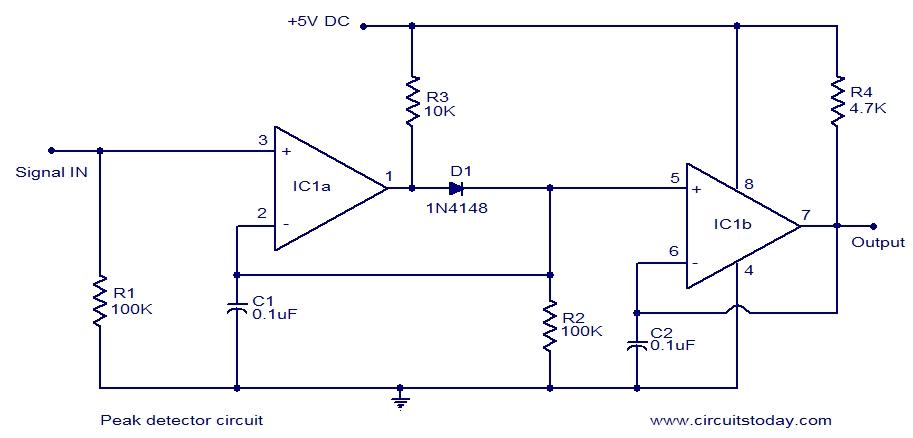
LM339-based peak detector circuit. Simple and easy to construct. Operates from a 5V DC single supply. LM339 is a dual comparator. The LM339-based peak detector circuit is designed to capture and hold the peak value of an input signal. This...
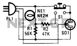
If residing in a cold climate, it is reassuring to confirm the functionality of an engine-block heater. This device indicates whether the heater is operational. To use, connect PL1 to a power outlet; the NE1 indicator should illuminate. Next,...
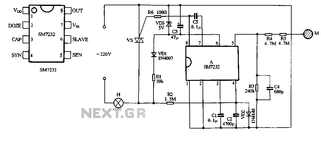
The core component of the circuit is the dimmer, utilizing the SM7232 integrated circuit. The pin configuration includes: 1) VDD, the positive power supply terminal; 2) DOZE; 3) CAP; 4) SYN, which synchronizes input power frequency using an internal...
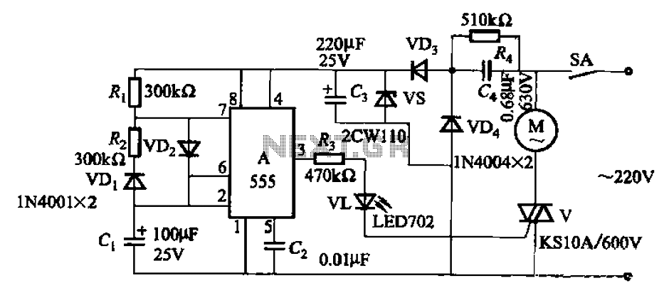
The circuit depicted in Figure 3-16 utilizes a 555 IC (Integrated Circuit) as the control element. It features a capacitive step-down circuit and incorporates a bidirectional thyristor (V) for intermittent motor control operation. By adjusting the resistance values of...
The filter consisting of resistors R1, R2, and capacitor C1 integrates the PWM waveform. The purpose of the operational amplifier appears to be that of a non-inverting amplifier, with the gain determined by resistors R6 and R7. However, the...
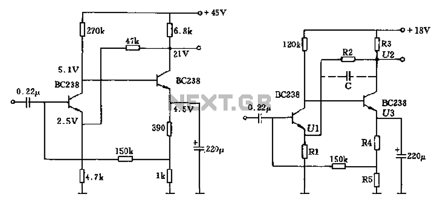
The circuit characteristic involves the elimination of external input resistors, which reduces the influence on the stabilization of the working point. It also employs two DC negative feedback loops. Additionally, the output from the second stage connects to the...