
Analog Compensation Circuit for PT100 RTD Temperature Sensor
Compensation for the nonlinearity of a PT100 RTD (Resistance Temperature Detector) is essential for achieving accurate temperature measurements. The PT100 RTD exhibits a nonlinear response to temperature changes, which can lead to measurement errors if not properly addressed.
Digital methods for linearization often involve the use of microcontrollers or digital signal processors (DSPs) that apply algorithms to correct the nonlinear response. These algorithms can include polynomial fitting, lookup tables, or spline interpolation to map the nonlinear characteristics of the PT100 to a linear output. The implementation typically requires an analog-to-digital converter (ADC) to sample the RTD output, followed by processing the data using the chosen algorithm, and finally outputting the corrected digital signal.
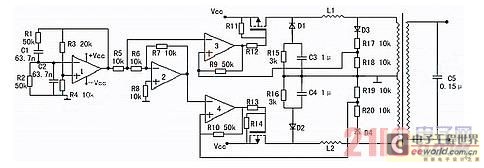
Analog methods may involve the use of operational amplifiers (op-amps) configured in specific arrangements to create a linear output based on the RTD resistance. This can include using resistor networks or feedback loops to shape the response curve. The choice between digital and analog methods depends on the specific application requirements, including factors such as cost, complexity, and desired accuracy.
In summary, both digital and analog techniques are viable for compensating the nonlinearity of PT100 RTDs, with each method offering distinct advantages and considerations for implementation.There are some digital and analog that can be used for compensating a PT100 RTD nonlinearity. We can implemented the digital linearization by implementing the. 🔗 External reference
Related Circuits
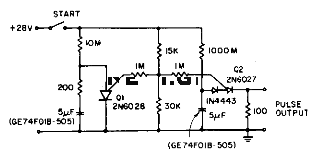
The circuit reduces the effective peak current of the output PUT, Q2. It allows the capacitor to charge with a high gate voltage and periodically lowers the gate voltage. When Q1 fires, the timing resistor can be set to...
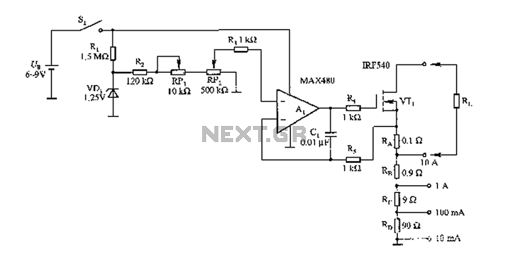
The FIG load test is a control circuit designed for external loads up to 10A, commonly utilized in drive test power applications, power amplifiers, LED solenoids, and relays. It is capable of handling various resistive loads and features a...

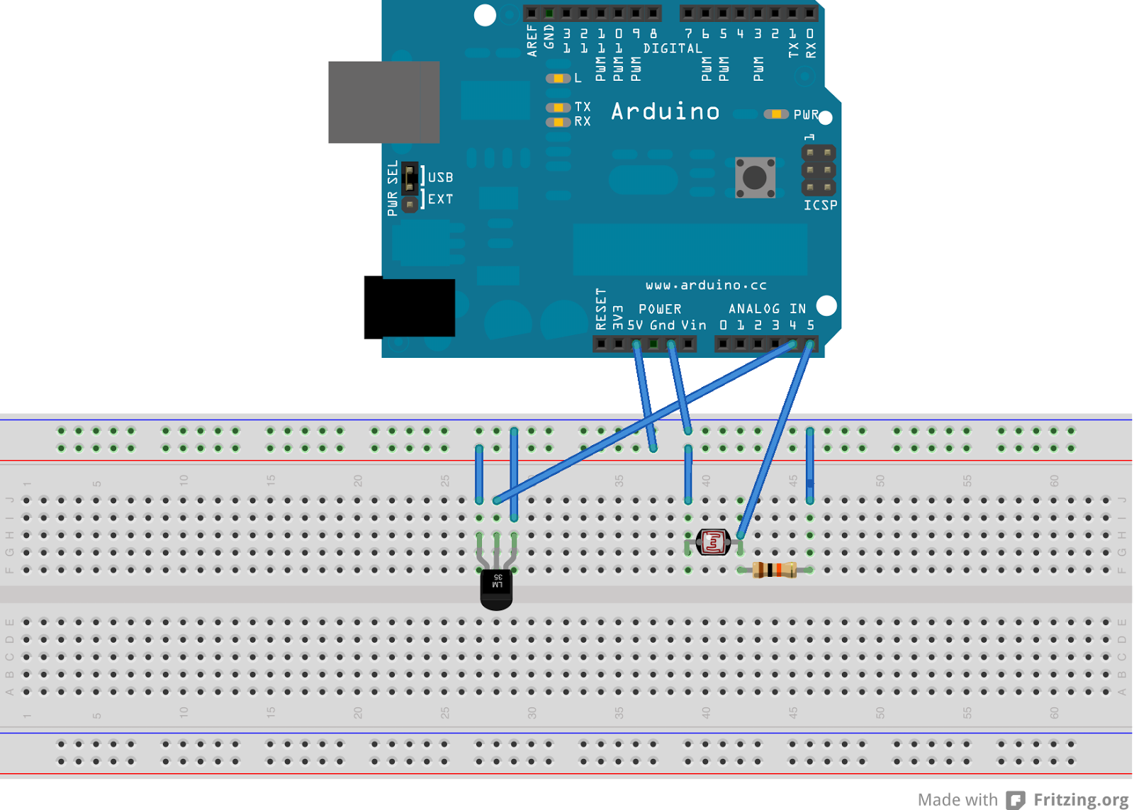
This is a simple smoke alarm circuit using a timer IC, the NE555. The circuit operates by illuminating a Light Dependent Resistor (LDR) with a lamp. When smoke obscures the light from the lamp, the resistance of the LDR...
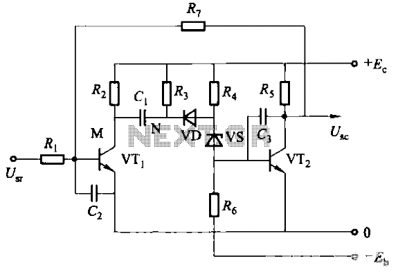
Rechargeable ago memory circuit. Before the memory circuit is activated, a delay reset circuit is utilized. When the input signal triggers an action, timing begins, and after a specified delay, the circuit reverts to its original state. During this...
This device transmits data regarding the state of an office to Twitter, as it is deemed slightly more relevant than sharing similar information about a residence. It holds potential significance for biodiversity-related activities, especially when integrated with long-range WiFi...
The inverter is a device that converts direct current (DC) from a battery or storage battery into alternating current (AC), typically at 220 volts and 50 Hz, producing either sine waves or rectangular waves. It serves as a common...