
analog delay line (echo and reverb)
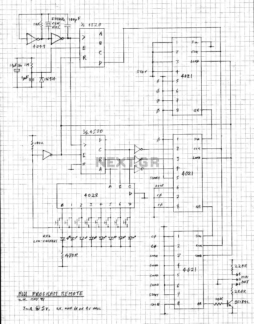
The described circuit operates within a clock frequency range of 5 kHz to 50 kHz. This frequency range is critical for ensuring that the circuit can adequately process audio signals, as it must be at least twice the maximum audio frequency to satisfy the Nyquist theorem. Typically, audio signals can reach frequencies up to 20 kHz; therefore, the minimum clock frequency of 40 kHz is necessary to avoid aliasing and ensure accurate signal representation.
The delay time, adjustable from 51.2 ms to 5.12 ms, indicates the circuit's capacity to introduce a time lag in the processing of signals. This feature can be utilized for various audio effects such as echo or reverb, where the delayed signal is mixed with the original to create a fuller sound.
In practical terms, the clock signal can be generated using a 555 timer IC configured in astable mode or by employing a microcontroller with a PWM output that can be fine-tuned to achieve the desired frequency. The delay can be implemented using a digital delay line, which can be constructed using shift registers or dedicated delay line ICs.
The circuit should also include appropriate filtering components to manage the frequency response and minimize noise. Capacitors and resistors may be utilized in conjunction with operational amplifiers to shape the signal and ensure that it remains within the desired frequency range.
Overall, careful consideration must be given to the selection of components to maintain signal integrity and achieve the desired performance within the specified frequency and delay parameters.E clock frequency between 5 and 50 kHz, delay time can be set between 51. 2 and 5. 12 ms. The clock frequency must be at least twice the highest audio frequency. 🔗 External reference
Related Circuits
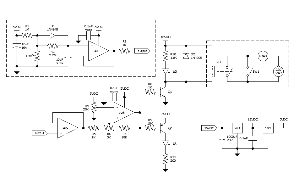
Approximately ten days ago, an all-linear automatic night light circuit was installed to control the lights in the living room. The circuit comprises three operational amplifiers (op-amps): two configured as voltage followers and one as a comparator. As depicted...
S/PDIF is an acronym for Sony /Philips Digital Interface (or Sony /Philips Digital Interconnect Format). The full specification for the S/PDIF interface consists of hardware and software, but only the hardware side will be discussed here - the software...
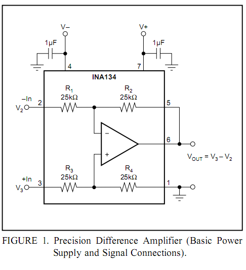
Burr-Brown DRV134 audio balanced line receiver schematic PCB/kit available? There is an interest in creating a balanced line receiver using the DRV134. The Burr-Brown DRV134 is an integrated circuit designed for audio applications, specifically for converting unbalanced audio signals...
The circuit is capable of measuring frequencies ranging from 1.5 kHz to 500 kHz by connecting different capacitors, C1 to C6. It can handle a maximum frequency of up to 1 MHz. Transistor T1 serves as the integrator, with...

A repertory dialer phone contains a library of phone numbers that can be entered and dialed, allowing access to up to fifteen frequently used numbers. It also includes the capability to store the last dialed number or an additional...
The 60 Watt linear amplifier is a simple all solid-state circuit using power MOSFET IRF840. The IRF series of power transistors are available in various voltage and power ratings. A single IRF840 can handle a maximum power output of...