
All-analog automatic night light circuit

The automatic night light circuit features a well-structured design that utilizes operational amplifiers to achieve its functionality. The circuit's primary components include three op-amps: two configured as voltage followers to ensure high input impedance and low output impedance, facilitating effective signal transfer without degradation. The comparator op-amp is crucial for determining the light level threshold at which the circuit activates or deactivates the connected lighting system.
The sensor is strategically placed to avoid interference from artificial lighting, ensuring that it accurately detects ambient light conditions. The inclusion of a unity gain buffer is critical in maintaining signal integrity, especially over longer distances, where capacitance can significantly affect performance. The low-pass filter, enhanced by the diode, plays a vital role in smoothing out transient signals and ensuring stable operation.
In terms of load management, the circuit employs a push-pull configuration with complementary transistors to drive the relay, which is responsible for switching the AC load. This design choice allows for efficient control of higher voltage loads while maintaining electrical isolation from the control circuitry. The feedback mechanism provided by the indicator LEDs informs users of the current operational state and adjustments made to the potentiometers.
The circuit's inherent limitation regarding hysteresis is acknowledged, as it necessitates that the light level for turning off the load is greater than that for turning it on. This behavior may not align with user preferences in all scenarios, particularly in applications where lights are desired to turn off at lower ambient light levels. The transition to a microcontroller-based solution is presented as a viable alternative to overcome these limitations, allowing for greater flexibility and customization through digital signal processing.
In summary, the automatic night light circuit represents a sophisticated integration of analog components designed to provide reliable lighting control based on ambient light conditions. The transition to a microcontroller-based approach offers opportunities for enhanced functionality and adaptability, paving the way for future advancements in automatic lighting solutions.Some ten days ago I installed an all-linear automatic night light circuit to control the lights inside the living room. Circuit consists of three op amps-two used as voltage followers and a third as a comparator. As the schematic shows, all user adjustable controls are at the comparator-with one potentiometer to set the trip point and the other
pot to adjust the width of hysteresis band. The sensor circuit is located several meters away at a location where it can have a view of the outdoors without being blinded or fooled by indoor lights at night. The high impedance sensor and low pass filter must have a unity gain buffer (voltage follower) within millimeters/centimeters.
You can`t have it on the main control circuit board meters away. Trust me. I`ve tested this several years ago with and without a buffer and a (unshielded twisted pair) cable. The signal will be degraded and probably unusable without the follower. Notice the low pass filter includes a diode. It performs a very important and essential function. See my other automatic night light circuits for the explanation. Driving large capacitive loads can cause stability problems for voltage feedback op amps. As the load capacitance increases, the feedback loop`s phase margin decreases and the closed-loop bandwidth is reduced. This produces gain peaking in the frequency response, with overshoot and ringing in the step response.
A unity-gain buffer (G = +1) is the most sensitive to capacitive loads, though all gains show the same general behavior. When driving large capacitive loads with these op amps (e. g. , > 100 pF when G = +1), a small series resistor at the output improves the feedback loop`s phase margin (stability) by making the output load resistive at higher frequencies.
(DS21810F, 2008, p. 14) Well, we`re working with essentially a DC signal and I have no idea of how much capacitance there is in the cable, but I just added R3 to be sure. The hysteresis circuit (R5, R6, R7) needs a low impedance source, thus A2 is used as a voltage follower-else R3 will foul up the resistor values for the hysteresis.
For a discussion of hysteresis in single-supply op amps read this. Equations are provided. A push-pull configuration using complementary transistors drives the relay and LEDs. A 12-volt relay is the output amplifier (and high-voltage isolator) which switches the 220VAC load. The relay is some 10 ten meters from the control circuit. Its normally open contacts are connected in parallel with the light`s wall switch-so this switch has to be off for the circuit to turn the load on/off automatically. Green and red indicator LEDs provide feedback when adjusting the pots. The shortcoming of this circuit-and for that matter all ANL circuits-is that the ambient light level at which the load is turned off must be higher than the light level at which it`s switched on.
In other words, incorporating a hysteresis-however small-forces the circuit to turn the load off at a brighter condition than for load switch-on. But in some cases (probably a majority) we want the lights off at the crack of dawn-i. e. , at a darker condition than when it was turned on. Someone may have already done so, but I haven`t yet come up with a way of doing this using linear components/ICs.
I don`t even know where to begin! Using a microcontroller on the other hand seems obvious and the simplest way to implement it. And that`s what I`ve been doing these past two days. Because it`s MCU-based the circuit itself is a no-brainer. The firmware`s where the brain-racking is. I`ve already installed a temporary circuit in place of the above all-analog one and will be checking its performance till week`s end. Given that I`m using an MCU-and all the computing power it`s got-I pared down the sensor subcircuit and eliminated the low pass filter.
Filtering is now performed digitally using algorithms. Pots are gone as well. Trip point is set using a momentary 🔗 External reference
Related Circuits
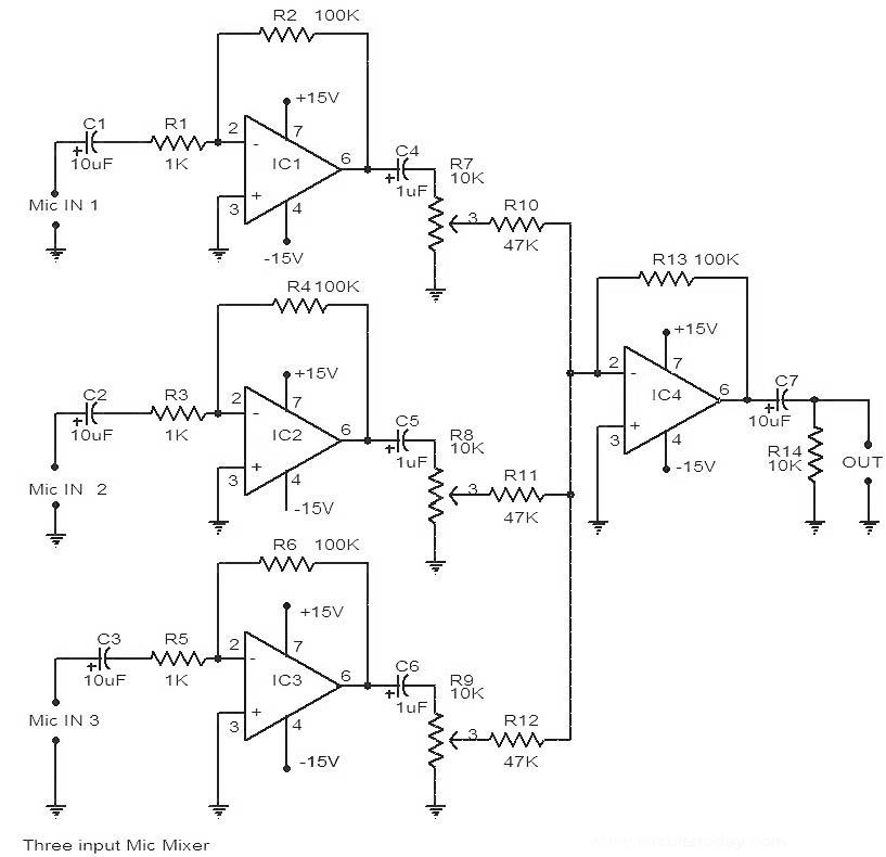
This is a circuit diagram of a 741 IC-based three-input microphone mixer circuit. A total of four 741 ICs are utilized, with IC1, IC2, and IC3 serving specific functions within the design. The circuit utilizes four operational amplifiers from the...

This is a simple design schematic for a phase control circuit that regulates the power delivered to an AC load. The phase control circuit modifies the AC waveform, allowing for variations such as full cycle, half cycle, zero cycle,...
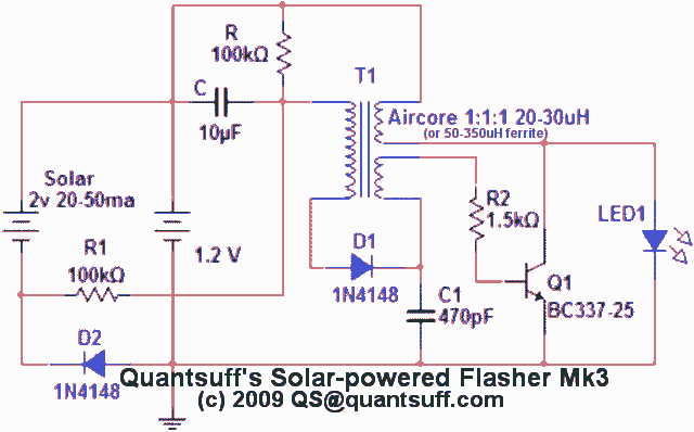
This circuit is a single transistor flyback (Joule Thief) circuit that features a third coil. With it, flash duration and brightness are significantly enhanced. The single transistor flyback circuit, commonly known as a Joule Thief, is designed to efficiently convert...
Here is a simple schematic of a TV transmitter circuit, or video transmitter circuit, capable of broadcasting in the VHF range from 60 to 200 MHz. The input video source can be any CCD camera or VCR. The output...
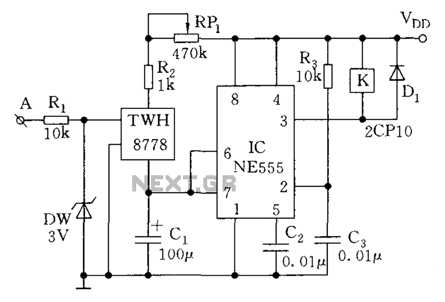
The count switching circuit consists of an electronic switch and a pulse delay circuit for control. The count switching circuit is designed to manage the switching of signals in a controlled manner. The electronic switch serves as the primary component...
Battery discharge leads to plate acidification, negatively impacting the battery's lifespan. To address this issue, a specialized micro-power battery over-discharge protection circuit has been designed. The circuit features a very low detection current (1.1 mA). Once the protection circuit...