
Analog IO Protection
The I/O Filter Wildcard is designed to facilitate various analog signal processing tasks, making it a versatile tool in electronic prototyping. Its architecture supports extensive customization, allowing engineers to tailor the filtering and conditioning processes to specific application requirements. The independent filtering capability of each I/O line ensures that signal integrity is maintained, which is critical in high-precision environments. The inclusion of both through-hole and surface-mount component options enhances flexibility in component selection based on size, performance, and power handling characteristics.
The schematic representation in Figure 1 provides a clear layout of the circuit pathways and component placements, ensuring that users can effectively visualize the design and functionality of the I/O Filter Wildcard. The careful arrangement of components and the provision for power and ground distribution demonstrate a well-thought-out approach to circuit design, facilitating ease of use and integration into larger systems. The ability to connect multiple Wildcards through the designated headers allows for scalable designs, accommodating more complex signal processing needs as required.
Overall, the I/O Filter Wildcard serves as an essential component in the development of robust electronic systems, providing the necessary tools for effective signal management and conditioning in a wide range of applications.The I/O Filter Wildcard provides a convenient place for prototyping analog circuitry or for filtering, conditioning or protecting the I/O lines of other Wildcards. Twenty-four I/O lines can be independently filtered, or their signals can be combined in custom ways.
When connecting external signals for data acquisition, you should always filter yo ur input and output lines; this will provide the best reliability and longevity for your instrumentation. Two 24-pin connectors are used for input and output; one generally mates to the field connector of a Wildcard I/O module, while the other connects to your external signals.
A third connector accommodates the Wildcard Bus, which can be used for power and ground. Up to four through-hole and four surface-mount components can be soldered onto the board to filter each of the 24 I/O lines. The I/O Filter Wildcard is a nearly blank prototyping board with a sea of holes for mounting components and three 24-pin headers.
The headers/connectors are used as follows: The Wildcard Bus connector is a 24-pin stacking/go through header/socket that allows the I/O Filter Wildcard to stack on other Wildcards. You can use the power and ground signals on it to power your custom circuitry or to provide signal references.
The Wildcard Field (output) connector is a 24-pin header that you can cable to any other Wildcard Field header. The side of the Wildcard where H3 resides is usually called the front of the Wildcard. The greyed-out pins on the Wildcard bus, H1, would not usually be used; only those shown in bold, the power and ground connections, would generally be needed.
If you are filtering inputs to a Wildcard, for each of the 24 I/O lines, you generally apply a signal to H2, the I/O (Input) Connector, you mount custom circuitry on the board to filter the signal, and the filtered signal is delivered to a corresponding pin on H3, the Wildcard Field Connector (Output). If you are conditioning outputs from a Wildcard, then the H3 connector becomes the input to the board, and the H2 connector the output.
Of course, if it is more convenient you are free to connect H2 to a Wildcard filed header and H3 to your external devices. Signals may flow in either direction between H2 and H3 what is important is that there is a one-to-one correspondence between the 24 pins on H2 and H3.
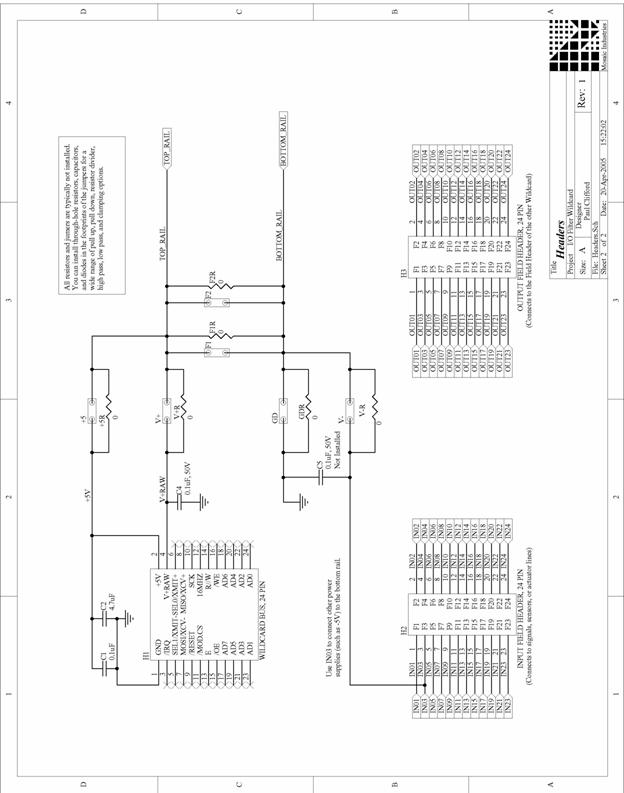
Figure 1 shows the schematic for four of the 24 circuits of the I/O Filter Wildcard; the others are identical. Also shown in Figure 1 are power and ground distribution circuits common to all the 24 channels. Fig. 1 I/O Filter Wildcard Schematic showing positions for through-hole components. For each through-hole component (e. g. , labeled 1A, 1C, 1E, 1G) there are also parallel pads for surface mount components (e. g. , labeled 1B, 1D, 1F, 1H) not shown here. Of the 24 identical channels, channels 1, 2, 3, and 24 are shown. Up to four through-hole or surface-mount components may be connected per circuit, or if both types are used up to eight circuit components may be used as shown below in Figure 2.
Some components connect the input pins to the output pins, while other components connect the signal path to either of two rails, a top rail, generally used for the positive power supply, and a bottom rail, generally used for the circuit ground. Figure 1 also shows several options for deriving the top and bottom rails. The top rail may be connected to the +5V or the V+RAW supplies by jumpering the pads (i. e. , connecting a wire or zero ohm resistor) labeled V+ or +5. Similarly, the bottom rail can be connected to the Wildcard Bus ground, but jumpering the GD pads, or to a user supplied input on pin 3 of H2, by jumpering V-.
The user supplied input would be generally used if a negative voltage is desired. These rails may be filtered by using resistors or inductors in place of the zero ohm jumpers and installing capacitors at positions F1 and/or F2. Or they can be protected agai 🔗 External reference
Related Circuits
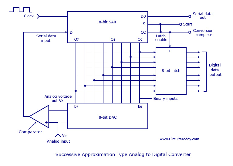
Analog to Digital Converters - Successive Approximation Type Analog to Digital Converter, working, circuit diagram. The Successive Approximation Register (SAR) Analog to Digital Converter (ADC) is a widely used type of ADC that converts an analog signal into a digital...
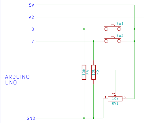
Flicker-free updating of analog input and the status of switches using Ajax and the Arduino Ethernet Shield. The Arduino Uno is configured as a web server. The described system utilizes an Arduino Uno microcontroller, which operates as a web server...
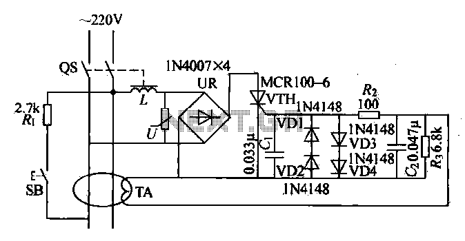
Current leakage protection is the most commonly used and effective leakage protection device. Current leakage protectors can be divided into electromagnetic and electronic types. The zero-sequence current transformer serves as the detection element, while electromagnetic leakage protection uses a...
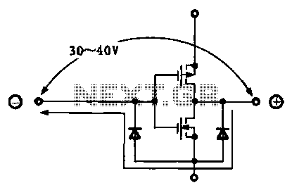
Due to the varying conditions of different input signals, when an abnormal voltage is applied to the pin, protection circuits are designed to create a circuit path that secures the internal protection of large-scale integration (LSI) circuits. The structure...
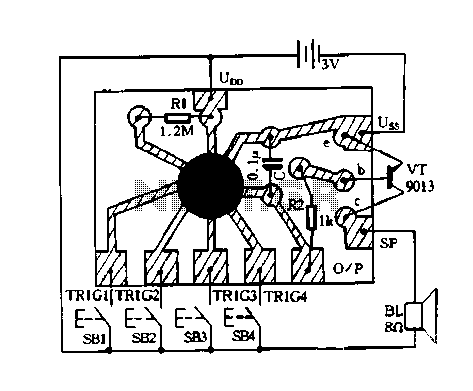
Constantly changing light and sound analog controller circuit 07 The circuit described is an analog controller designed to modulate light and sound in a dynamic manner. This circuit utilizes various electronic components to create an interactive experience where both light...
This device supports up to 8 analog inputs with a voltage range of 0 to 5 volts, generating selectable MIDI control output commands. The analog inputs can include rotary or slider potentiometers connected to the 0 to 5 volts...