
Various protection circuit structure and working principle diagram
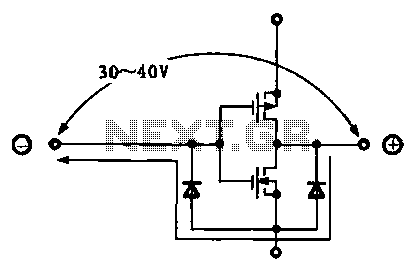
The protection circuit for LSI devices is essential for safeguarding the integrity of the integrated circuit against voltage spikes and other anomalies that may occur during operation. The circuit typically consists of several key components, including diodes, resistors, and capacitors, which work together to divert excess voltage away from sensitive components.
When an abnormal voltage is detected at the input pin, the protection circuit activates. Diodes are often employed in a clamping configuration to redirect excessive voltage to ground, effectively limiting the voltage that reaches the LSI. This prevents damage that could result from transient voltages or electrostatic discharge (ESD).
The resistors in the circuit can serve multiple purposes, such as current limiting and voltage division, ensuring that the voltage levels remain within safe operating ranges. Capacitors may also be included to filter out high-frequency noise, providing additional stability to the circuit.
Overall, the design of the protection circuit must take into account the specific voltage levels and signal characteristics of the application. Proper selection of components and configuration is crucial to ensure reliable operation and to extend the lifespan of the LSI device. This protective mechanism is a vital aspect of modern electronic design, particularly in environments where signal integrity and reliability are paramount.Due to the different circumstances of the various input signals, when the pin is applied between the abnormal voltage, protection circuits to form a circuit path from while LSI (large scale integration) circuits internal protection. Structure and principles of its protection circuit is shown
Related Circuits
This simple circuit is based on the well-known integrated circuit LM3915. The main characteristic of this integrated circuit is its ability to manage 10 Light Emitting Diodes (LEDs) in a logarithmic scale, with a 3dB difference between the LEDs,...
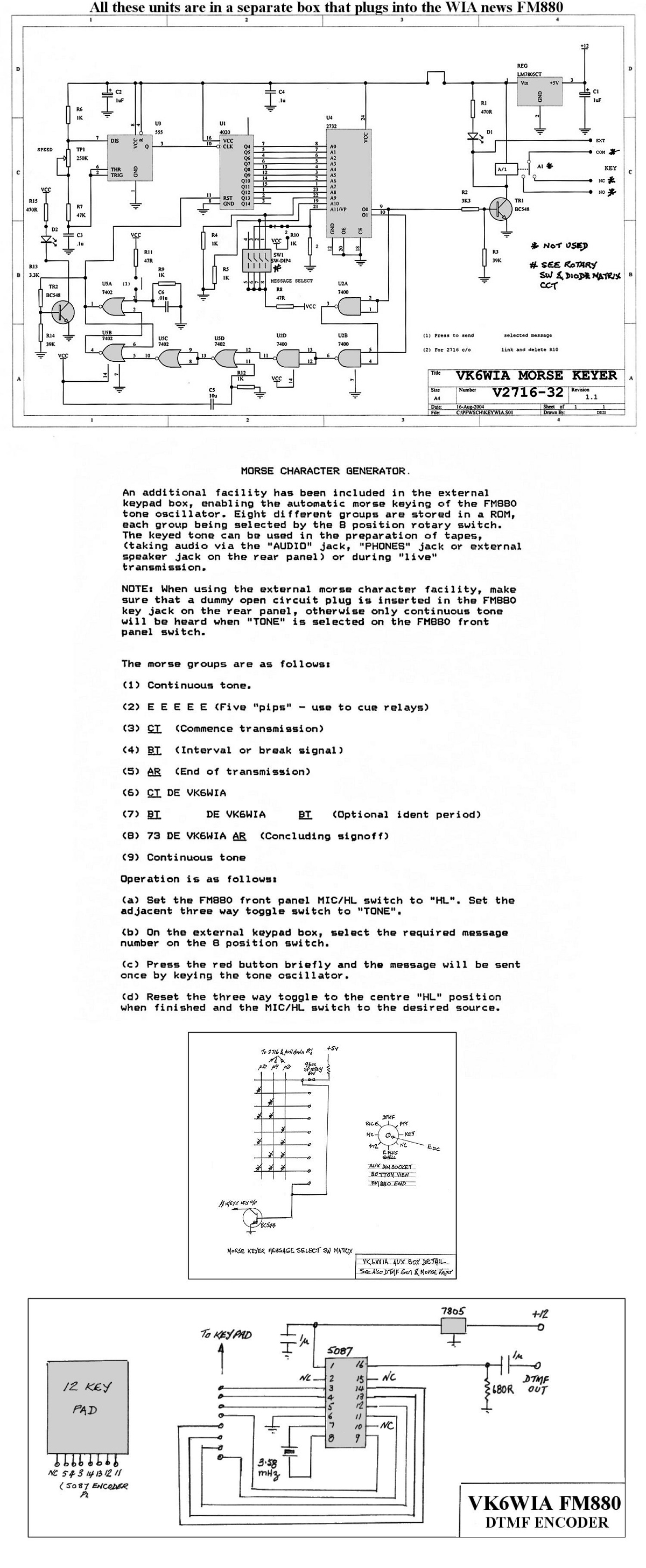
The unit is based on a PHILIPS FM880 link transceiver originally supplied to a Telecom Australia specification for telephone applications in remote areas of Australia. The FM880 is part of a family of equipment that includes the PHILIPS FM828/FM814...

Any NPN transistor can be used. The author used a 2N3904, but a 2N2222A should work just as well. A good, low noise transistor would be even better. Some radios only have three connections to their ferrite bar antenna:...
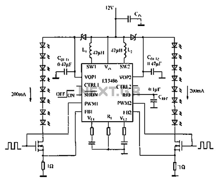
The automotive LED driver circuit diagram utilizes the LT3486. The LED is employed in the car's central high-mounted stop lamp (CHMSL), providing advantages such as faster achievement of the set brightness, higher efficiency, longer lifespan, and simplified design and...
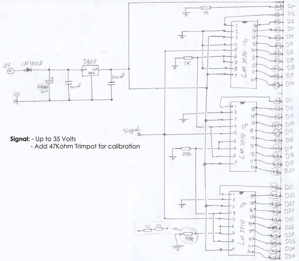
The circuit schematics operate at 12 Volts, sourced from a car battery. The ground connection is tied to the car chassis, while the signal is received from a sensor connected to a stepper motor. The No. 5 pin of...
The hum noise is produced by an electronic device with improper design. To address this issue, it is essential to identify the source of the hum. This involves checking the grounding, cabling, casing, and other factors that may contribute...