
Constantly changing light and sound analog controller circuit 07
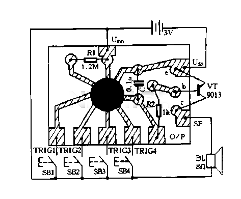
The circuit described is an analog controller designed to modulate light and sound in a dynamic manner. This circuit utilizes various electronic components to create an interactive experience where both light intensity and sound output can be adjusted in real-time. The core of the design typically includes operational amplifiers, resistors, capacitors, and possibly transistors to facilitate the modulation processes.
In this circuit, light modulation may be achieved through the use of light-emitting diodes (LEDs) or incandescent bulbs, which can be controlled by varying the voltage supplied to them. The sound output could be generated using a piezoelectric speaker or a small audio amplifier, where the frequency and amplitude of the sound can be altered based on the input signals from the controller.
To implement the constantly changing aspect, the circuit may incorporate a feedback mechanism, such as a light-dependent resistor (LDR) or a microphone, which detects changes in ambient light or sound levels. The feedback is processed through the operational amplifiers, which adjust the output signals accordingly. Additionally, the inclusion of a microcontroller can enhance the circuit's capabilities by allowing programmed patterns of light and sound changes, enabling more complex interactions.
Overall, this circuit exemplifies a versatile approach to creating an engaging environment through the integration of light and sound, demonstrating the principles of analog control in electronic design.Constantly changing light and sound analog controller circuit 07
Related Circuits
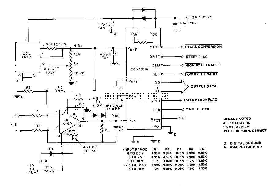
The BiMOS CA3140 operational amplifier offers excellent orientation capabilities for high bandwidth signal inputs and can swiftly adjust the energy output at its terminal CA33IO WINE. The CA3140 can also operate close to the negative supply rail. If the...
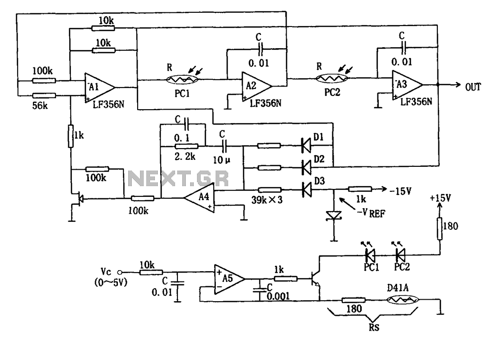
The wideband sinusoidal voltage-controlled oscillator circuit is designed such that the oscillation frequency is determined by an integrating resistor R and a capacitor C. The voltage-controlled oscillator is constituted by the applied control voltage Vc and a control resistor...
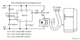
This is a simple freeze protector circuit diagram, also known as a timing circuit. It serves as a hobby project for beginners. This circuit can automatically operate any device after a fixed time once AC power supply is restored....
The purpose of this circuit is to animate shop windows using a capacitive sensor positioned behind a postcard-like banner. The card is placed against the glass inside the shop window, allowing visitors to activate the relay by placing their...
This is an 8-bit up/down counter that, together with the "8-bit binary to 256 decimal (1 of 256) decoder," forms a run light. The circuit utilizes an 8-bit up/down counter, which is capable of counting both upwards and downwards...

This is a design of the circuit diagram for an RS422 interface. Connector K1 is connected to the serial port of the PC, and power for the PC side of the circuit is obtained from the signal lines DTR...
Warning: include(partials/cookie-banner.php): Failed to open stream: Permission denied in /var/www/html/nextgr/view-circuit.php on line 713
Warning: include(): Failed opening 'partials/cookie-banner.php' for inclusion (include_path='.:/usr/share/php') in /var/www/html/nextgr/view-circuit.php on line 713