
analog light dimmer circuit connected to microcontroller

The light dimmer circuit utilizing the PIC12C508 microcontroller serves to control the brightness of a light source through pulse width modulation (PWM). The circuit typically includes the microcontroller, a TRIAC for controlling the AC load, a zero-crossing detector, and associated passive components to ensure proper operation.
The PIC12C508 microcontroller, known for its compact size and low power consumption, can be programmed to generate PWM signals that adjust the phase angle of the AC waveform. This modulation technique allows for fine control of the light intensity. The zero-crossing detector is crucial, as it synchronizes the TRIAC firing with the AC waveform, ensuring that the TRIAC is triggered at the appropriate moment to achieve the desired dimming effect without causing flicker.
In terms of circuit design, the microcontroller's output pin is connected to the gate of the TRIAC, while the zero-crossing detector provides feedback to the microcontroller to adjust the timing of the PWM signal. Resistors and capacitors are used to filter and stabilize the signals, ensuring reliable performance. Additionally, safety features such as snubber circuits may be implemented to protect the TRIAC from voltage spikes.
Modifications to this circuit may involve adjusting the PWM frequency, changing component values for different dimming ranges, or enhancing the user interface for better control. Overall, the circuit is designed to provide efficient and effective light dimming capabilities while maintaining user safety and circuit integrity.Hello everyone, I need help to modify this light dimmer circuit which is connected to PIC12C508 microcontroller. This circuit is designed for the.. 🔗 External reference
Related Circuits
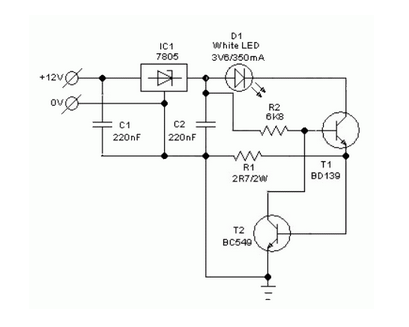
A simple and safe white LED driver circuit has been designed for use in 12V automobiles, allowing for the efficient operation of standard high-efficiency white LED modules powered by automotive battery systems. The circuit utilizes a fixed voltage regulator...

Simple two-wire remote monitoring unit with a three-LED level display, powered by a 9V battery. The entire project was developed at the request of a friend. The remote monitoring unit is designed to provide a straightforward solution for level indication...

The MC33411 900 MHz Analog Cordless Phone Baseband system is designed to meet the specifications of a 900 MHz Analog cordless telephone system. It includes three Phase-Locked Loops (PLLs). Two of these PLLs are intended for use with external...
This 1 Hz and 2 Hz generator or oscillator is constructed using a 4060 IC as the oscillator and a 14-bit counter. To achieve a 1 Hz signal from the 4060, a 1/2 4013 flip-flop is utilized. This circuit...

LMD18245 bipolar stepper motor driver circuit design using few electronic parts The LMD18245 is a versatile bipolar stepper motor driver designed to control stepper motors with precision and efficiency. This circuit utilizes a minimal number of electronic components, making it...
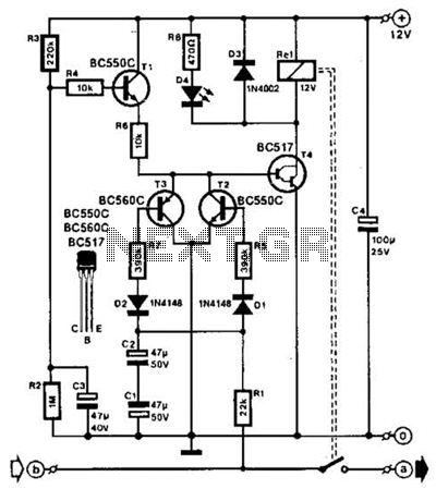
A speaker system can be safeguarded against amplifier failure by detecting DC voltages on the speaker line (a-b). The circuit is capable of sensing both positive and negative DC voltages. In such instances, a relay activates to disconnect the...
Warning: include(partials/cookie-banner.php): Failed to open stream: Permission denied in /var/www/html/nextgr/view-circuit.php on line 713
Warning: include(): Failed opening 'partials/cookie-banner.php' for inclusion (include_path='.:/usr/share/php') in /var/www/html/nextgr/view-circuit.php on line 713