
1 Hz Generator and 2 Hertz Oscillator Circuit
The circuit operates by leveraging the 4060 integrated circuit, which combines an oscillator and a binary counter. The oscillator portion of the 4060 is typically configured to produce a square wave output that can be divided down to lower frequencies. In this design, the output frequency is set to 2 Hz, which is subsequently divided by two using the 1/2 4013 flip-flop to yield a stable 1 Hz output signal.
The 4060 IC operates based on an external resistor-capacitor (RC) network that determines the oscillation frequency. The frequency can be calculated using the formula:
\[ f = \frac{1}{2 \cdot R \cdot C \cdot (N + 1)} \]
where \( R \) is the resistance in ohms, \( C \) is the capacitance in farads, and \( N \) is the division factor set by the counter. The resulting square wave output from the 4060 can be fed into the 4013 flip-flop, which is configured in toggle mode. This configuration divides the frequency by two, allowing for the generation of a precise 1 Hz signal.
The output of the circuit is a rectangular waveform that oscillates between 0V and the supply voltage, making it suitable for various applications, including clock generation for digital circuits, timing applications, and frequency modulation. Proper decoupling capacitors should be placed near the power supply pins of the ICs to ensure stable operation and minimize noise. Additionally, the circuit should be designed with appropriate power ratings and tolerances to ensure reliability during operation.This 1 Hz and 2Hz generator or oscillator is built with 4060 as an oscillator and a 14 bits counter. To obtain a 1Hz signal after 4060 we use 1/2 4013. This circuit provides a rectangular voltage with a amplitude between 0V and the power supply voltage. 🔗 External reference
Related Circuits
Stabilized DC Power Supply with Short-Circuit Indication. The circuit provides four distinct regulated DC outputs (12V, 9V, 6V, and 5V) along with an unregulated 18V DC output, selectable via a rotary switch S2. The chosen output is displayed on...
Generating long delays of several hours can be achieved using a low-frequency oscillator and a binary counter. A single Schmitt Trigger inverter stage (1/6 of 74HC14) functions as a square wave oscillator, producing a low frequency of approximately 0.5...
This page outlines the development of electronics for displaying a monochrome video image on an electrostatic oscilloscope tube. This work complements the Electron Optics section in the Experiments category. The primary objective is to showcase a moving video image...
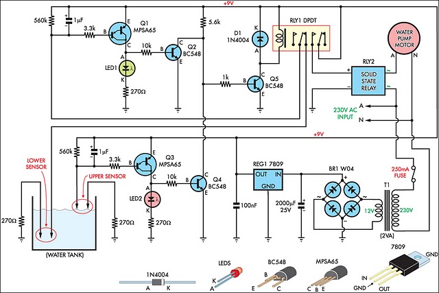
This circuit is designed to efficiently fill a header tank for a reticulated water supply on a farm. It supplies eight troughs located in various paddocks where water scarcity can have severe consequences for livestock. Previously, the tank was...
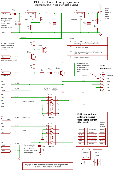
A PIC programmer circuit that operates using long cables from a PC to the programmer. The PIC programmer circuit is designed to facilitate the programming of PIC microcontrollers via a connection to a personal computer (PC) using extended cabling. This...
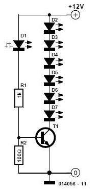
Its state is constantly changing, and this change affects the flow of current and voltage, which is visible with the two LEDs. The speed of the LED flasher can be adjusted with potentiometer P1. As an astable multivibrator, the...
Warning: include(partials/cookie-banner.php): Failed to open stream: Permission denied in /var/www/html/nextgr/view-circuit.php on line 713
Warning: include(): Failed opening 'partials/cookie-banner.php' for inclusion (include_path='.:/usr/share/php') in /var/www/html/nextgr/view-circuit.php on line 713