
LMD18245 bipolar stepper motor driver circuit design
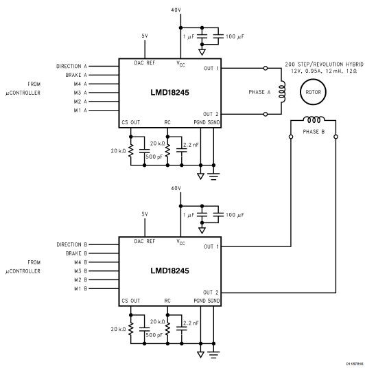
The LMD18245 is a versatile bipolar stepper motor driver designed to control stepper motors with precision and efficiency. This circuit utilizes a minimal number of electronic components, making it suitable for applications where space and cost are critical factors. The LMD18245 integrates power and control functionalities, enabling seamless operation of stepper motors in various configurations.
The circuit typically includes the LMD18245 driver IC, which can handle a wide range of input voltages and provides high current output, accommodating different stepper motor specifications. Additional components often involved in the design are resistors, capacitors, and diodes, which help in managing the input signals, filtering noise, and protecting the circuit from voltage spikes.
The design can be configured for both full-step and half-step driving modes, allowing for flexibility in motor control. Full-step mode provides maximum torque, while half-step mode offers smoother motion and increased resolution. The circuit can be controlled via a microcontroller or a dedicated stepper motor controller, which sends pulses to the LMD18245 to dictate the stepping sequence.
To ensure reliable operation, the circuit may incorporate thermal management features, such as heat sinks or temperature sensors, to monitor the temperature of the driver IC. Proper heat dissipation is critical to maintain performance and prevent thermal shutdown.
Overall, the LMD18245 bipolar stepper motor driver circuit design is an efficient solution for driving stepper motors in various applications, including robotics, CNC machines, and automation systems. Its simplicity and effectiveness make it a popular choice among engineers and hobbyists alike.LMD18245 bipolar stepper motor driver circuit design using few electronic parts 🔗 External reference
Related Circuits
Our programmable MP3 player has an interface to an LCD with a HD44780 controller. These are alphanumeric LCDs with one to 4 lines of text and 16 to 40 characters per line. However, these LCDs (and LCDs in general)...
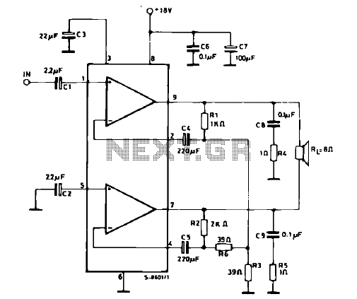
The schematic illustrates a 12 W Bridge Amplifier circuit diagram utilizing the TDA2007A, a class AB dual audio power amplifier. This amplifier is specifically designed for stereo applications in music centers, television receivers, and portable radios. As stated in...
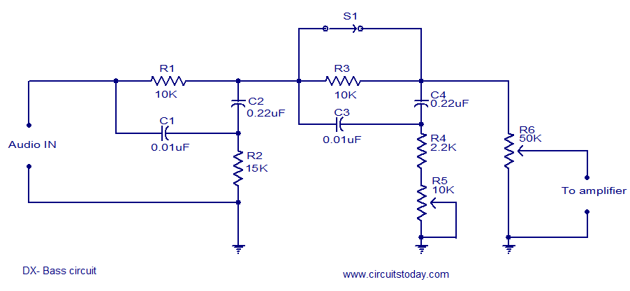
The circuit diagram of a passive DX bass circuit is presented, which is compatible with nearly all audio amplifiers. This design was created by Mr. Emmanuel Chipula from Malawi and submitted for publication. Laboratory tests confirmed satisfactory performance. Credit...
A 100W amplifier with a frequency range from DC to 500KHz features a photoelectric starting operational amplifier with high input impedance and high gain characteristics, enabling transformerless output power of 100W. The load current can reach up to 10A,...
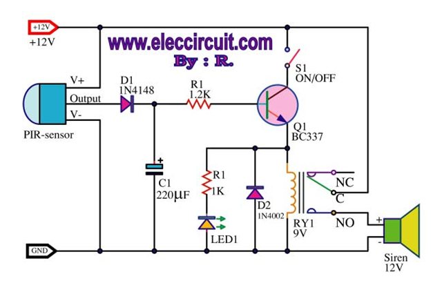
A motion detection alarm circuit utilizing a PIR sensor for motion detection. When movement is detected by the PIR sensor, it triggers a delay circuit, Q1, and other components. The motion detection alarm circuit is designed to provide an alert...
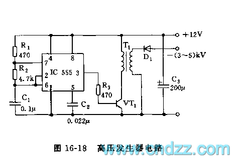
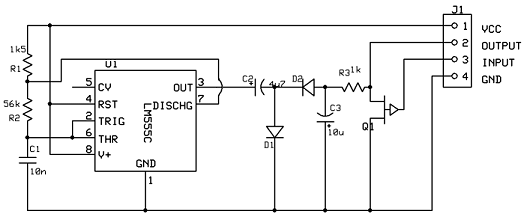
The high voltage generator depicted in figure 16-18 utilizes the 555 timer IC as its primary component. The oscillating voltage produced is enhanced through a step-up transformer. The astable multivibrator configuration comprises the 555 timer along with resistors R1...
Warning: include(partials/cookie-banner.php): Failed to open stream: Permission denied in /var/www/html/nextgr/view-circuit.php on line 713
Warning: include(): Failed opening 'partials/cookie-banner.php' for inclusion (include_path='.:/usr/share/php') in /var/www/html/nextgr/view-circuit.php on line 713