
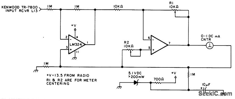
analog milliamp meter used as voltmeter
To implement this conversion effectively, a series resistor must be selected based on the desired voltage range and the specifications of the milliamp meter. The full-scale voltage (V_fs) represents the maximum voltage the meter will measure, while the full-scale current (I_fs) corresponds to the maximum current the meter can handle without damage.
In this case, for a 1 milliamp meter, the full-scale current is 0.001 A. To measure voltages up to 10 volts, the necessary resistance can be calculated using the formula:
R = V_fs / I_fs = 10 V / 0.001 A = 10,000 ohms.
This resistor should be connected in series with the milliamp meter. The combination allows the meter to display the voltage across the resistor instead of the current flowing through it, effectively transforming the milliamp meter into a voltmeter.
It is important to note that the resistor must be rated to handle the power dissipated across it, which can be calculated using the formula:
P = I^2 * R = (0.001 A)^2 * 10,000 ohms = 0.01 W or 10 mW.
A resistor with a power rating of at least 1/8 watt (0.125 W) would be suitable for this application, providing a safe margin above the calculated dissipation.
Overall, this simple modification allows for the repurposing of a milliamp meter as a voltmeter, broadening its utility in electronic measurement applications. Proper attention to the resistor's specifications ensures accurate readings and reliable performance.A milliamp meter can be used as a volt meter by adding a series resistance. The resistance needed is the full scale voltage reading divided by the full scale current of the meter movement. So, if you have a 1 milliamp meter and you want to read 0-10 volts you will need a total resistance of 10/.001 = 10K ohms..
🔗 External reference
Related Circuits
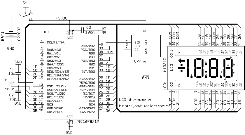
The circuit drives the LCD pins with 50% square waves. Each segment on this LCD is connected to the COM backplane and a separate pin. When a pin is driven in phase with the COM pin, the corresponding LCD...
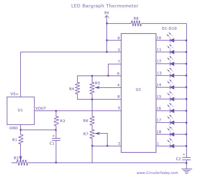
An LED thermometer that can function as a temperature sensor or temperature measurement circuit, utilizing the LM34 for Fahrenheit display or the LM35 for degree Celsius display. The LED thermometer circuit is designed to provide accurate temperature readings using either...
The A3008, when connected to the LWDAQ Multiplexer, may generate erroneous messages in the Data Receiver (A3018). To mitigate the rate of bad messages, set the A3008's local oscillator to either its minimum (DAC count 0) or maximum (DAC...
This circuit can be utilized in most FM VHF receivers, with the connection made from the FM discriminator. Each transmitted signal has a unique deviation signature, which can assist in identifying jammers. The described circuit is designed for integration into...
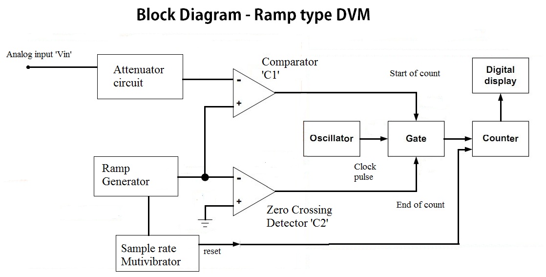
In the voltage-to-time conversion section, the analog input voltage is directed to the attenuation circuit. The attenuated signal is compared with the ramp signal generated by the ramp generator, as indicated in the block diagram, through the input comparator...
This simple-to-construct water fishing thermometer circuit is intended for use in sports applications, such as fishing contests. A sensor measures... This water fishing thermometer circuit is designed to provide accurate temperature readings of water, making it an essential tool for...