
DEVIATION METER
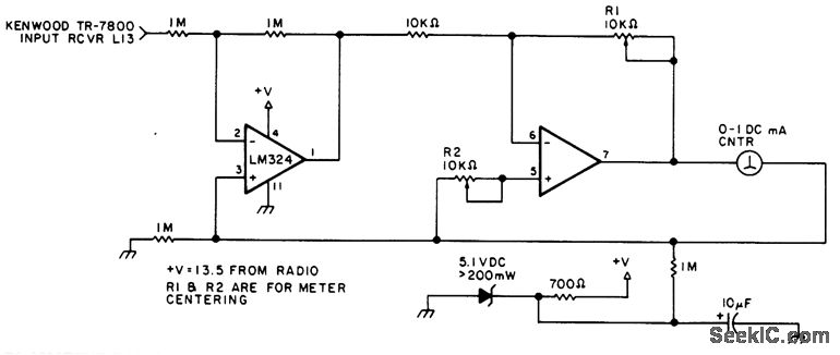
The described circuit is designed for integration into FM VHF receivers, serving as a tool for signal analysis and jamming detection. The connection point is established at the FM discriminator, a critical component responsible for demodulating frequency-modulated signals. By tapping into this point, the circuit can monitor the deviation of incoming signals.
In FM communication, each transmitted signal is characterized by a specific deviation from the carrier frequency, which is determined by the modulation of the signal. This unique deviation signature allows for the differentiation of signals even in the presence of interference. The circuit exploits this property to detect and analyze the characteristics of various signals, making it particularly useful for identifying and locating jamming sources.
The circuit may incorporate elements such as bandpass filters to isolate the desired frequency range, amplifiers to boost the signal strength, and a microcontroller or dedicated processing unit to analyze the deviation signatures. The output can be visualized through an oscilloscope or transmitted to a computing device for further analysis.
In summary, this circuit provides a robust solution for monitoring FM VHF signals, enabling users to distinguish between legitimate transmissions and potential jamming attempts based on unique deviation signatures. Its application is essential in scenarios where signal integrity is critical and interference must be identified and mitigated.You can use this circuit in most FM VHF receivers; the hookup is off the FM discriminator. Because every signal transmitted has its own deviation signature, this can be a red plusin hunting jammers 🔗 External reference
Related Circuits
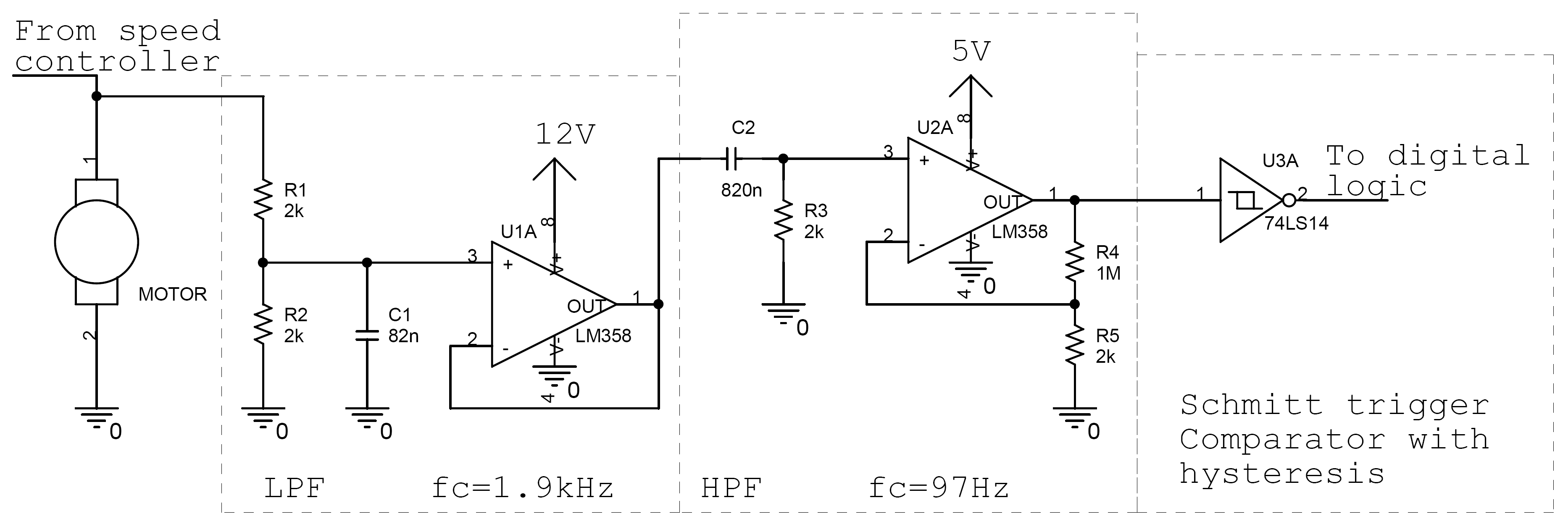
Controlling the speed of a motor is crucial in various applications, particularly in robotics. Numerous techniques exist for adjusting motor speed, each offering distinct advantages and disadvantages. This document outlines the construction of a motor controller that regulates the...
This sound level meter serves as an effective one-chip replacement for standard analog meters. It is entirely solid-state, ensuring durability and longevity. The circuit is built around the LM3915 audio level integrated circuit (IC) and requires only a minimal...
The circuit exhibits a flat frequency response ranging from approximately 20Hz to over 50kHz. The input sensitivity is set at 100mV for full-scale deflection on a 100µA meter. It is constructed using two common emitter amplifiers; the first stage...
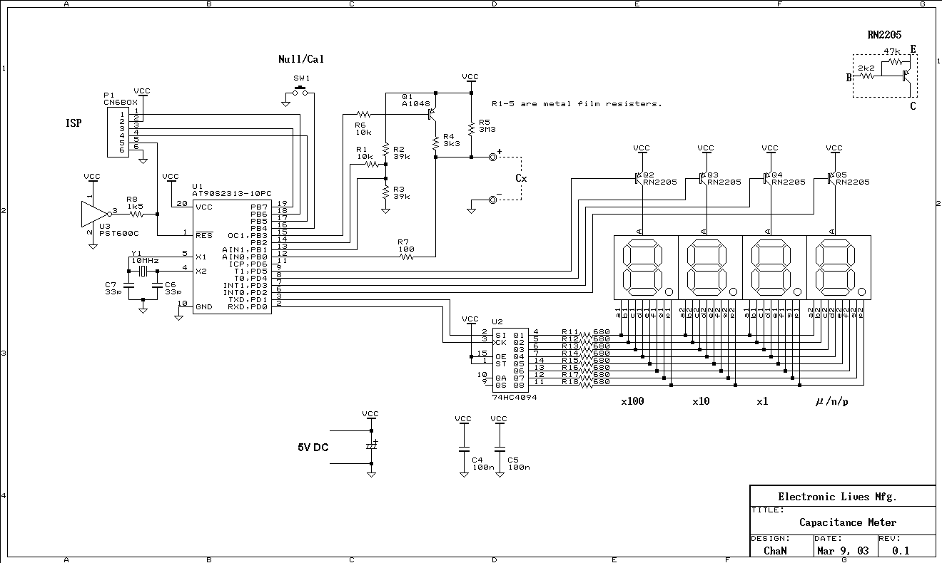
This is a simple capacitance meter which can measure capacitance value easy. There are some measurement methods for capacitance, at one time the capacitance was measured with a impedance bridge or a dip meter. Recently typical capacitance meters can...
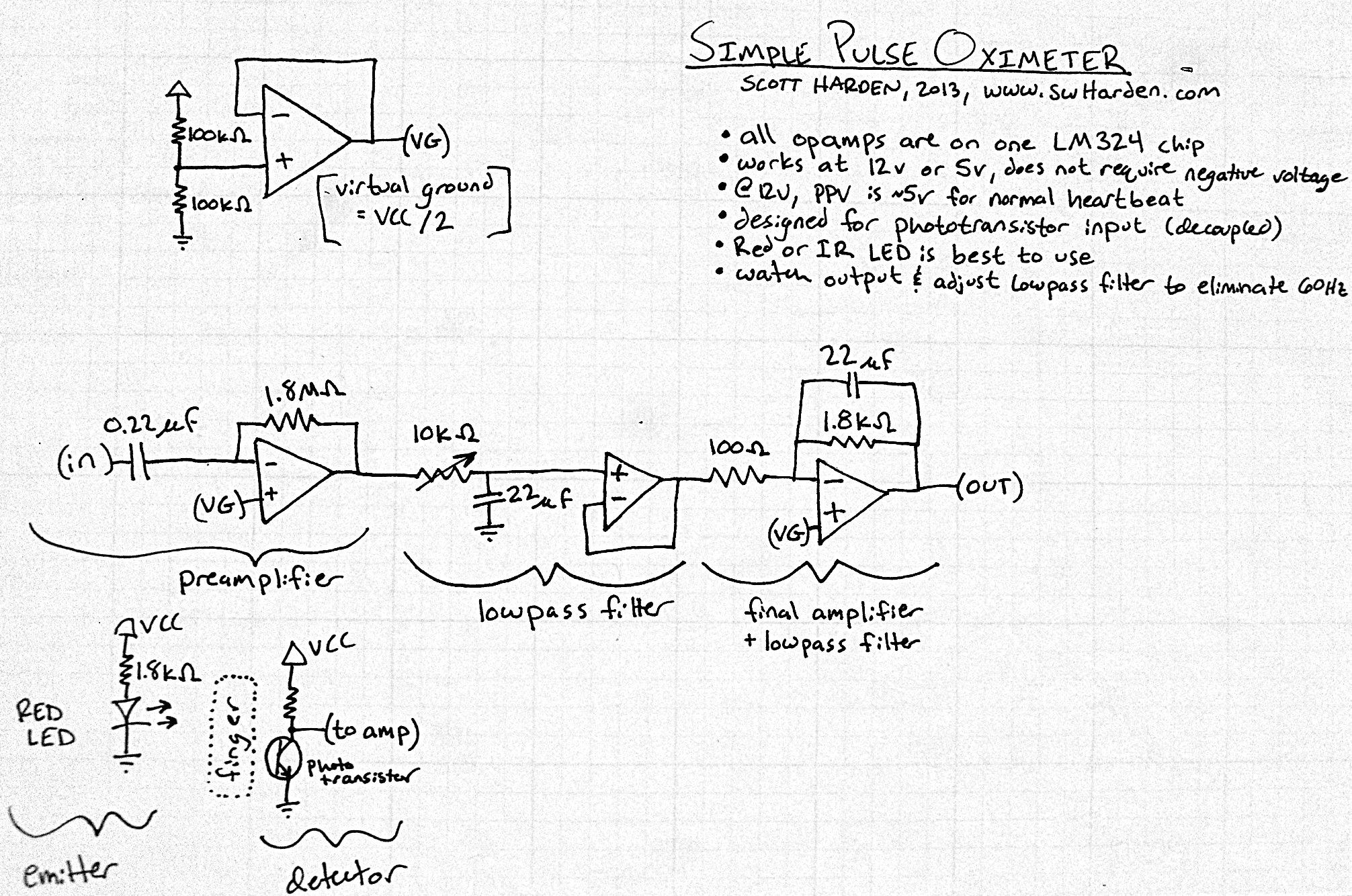
The input capacitor for the phototransistor at the bottom is responsible for feeding the operational amplifier (op-amp). However, the output from the phototransistor consistently remains between ground (GND) and the supply voltage (Vcc). The necessity for an input capacitor...
The circuit diagram illustrates a straightforward circuit design featuring 10 LEDs. It employs a series of half-wave rectification using the precision IC2 TL071, along with a single LM3915 IC that regulates the LEDs, functioning as a VU meter indicator....