
analog mv switch for digital meters
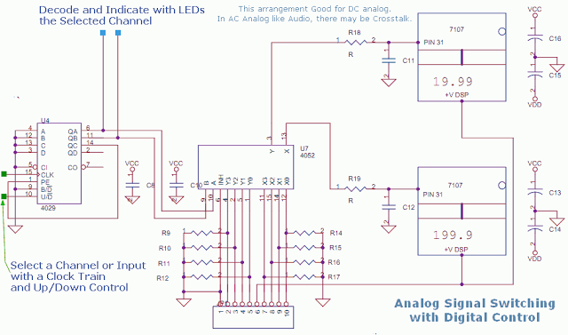
The circuit described involves a 4052 analog multiplexer, which is adept at switching multiple analog input signals to a single output channel. The requirement for low-impedance output from the operational amplifiers ensures that the multiplexer operates effectively without introducing significant loading effects that could distort the signals.
The use of resistors, while not essential, serves a critical role in maintaining signal integrity. A 100K resistor can be implemented to prevent floating inputs, which can lead to unpredictable behavior in the circuit. This precaution is particularly important in scenarios where the sensors may not be actively driving the input, ensuring that the multiplexer receives a stable reference.
In terms of signal conditioning, the operational amplifiers must be configured to amplify and scale the input signals appropriately before they reach the multiplexer. This step is crucial for ensuring that the dynamic range of the signals is compatible with the input specifications of the 4052. For instance, when using a shunt resistor for current sensing, the operational amplifier must be set up to convert the small voltage drop across the shunt into a larger, measurable signal. Similarly, when utilizing a current transformer for AC current measurements, the output must be conditioned to represent the RMS value of the AC signal accurately.
The voltmeter in this configuration incorporates an attenuator, which is essential for scaling down high voltage signals to levels suitable for measurement by the analog multiplexer. This attenuator ensures that the input to the multiplexer remains within its specified voltage range, preventing damage and ensuring accurate readings.
Overall, this circuit design is a robust solution for multiplexing multiple analog signals, with careful consideration given to signal integrity, conditioning, and measurement accuracy, making it suitable for a variety of applications in electronic instrumentation.This circuit uses a 4052 as a DC Analog Multiplexer, the inputs to this Mux must be from Low Impedance Output OpAmps. The Resistors Shown are not needed once the Signal Conditioning Opamps are connected. The Restors can be 100K to keep the inputs from floating, that will not load an opamp. The resistors can attenuate signals if sensors are directl y connected. The signals from sensors have to be amplified and corrected or scaled before reaching this Switched DVM. For Current a Shunt is the Sensor and for AC current a CT or current transformer is the sensor. Voltmeter has Attenuator as the `Sensor`. 🔗 External reference
Related Circuits
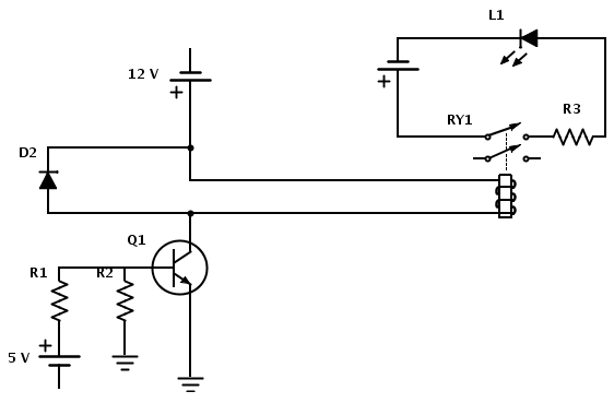
Create a circuit that enables the activation of a relay to control an LED. The relay operates at 12 V, while the available input voltage is 5 V. An NPN transistor will be utilized to switch the power to...
This is a straightforward circuit. The first stage functions as a crystal receiver, utilizing a germanium detector diode (such as 1N34, although AA119 is more commonly found in Europe); a silicon diode is not suitable. The operating frequency is...
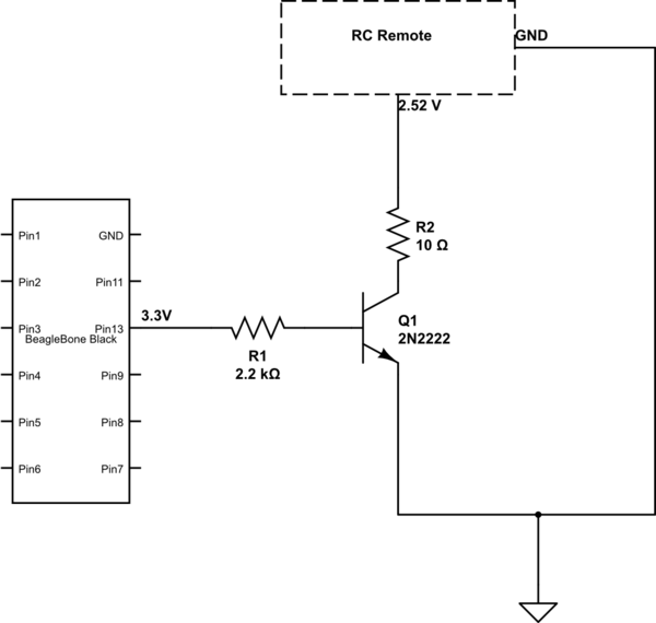
The remote control of an RC car was modified by extending wires from the backward, forward, left, and right switches. Grounding any of these wires completes the circuit and sends a signal to the car. The intention is to...
This circuit will light a lamp at a remote location when the doorbell switch is pressed. This circuit should only be used with the solenoid type doorbells; the electronic type that play tunes will not work here. It is...

The clock displays time in 5-minute intervals, with adjustable hour and minute settings. There is no alarm feature or AM/PM indicator. The clock face is constructed from two pieces of linoleum glued together for added thickness, though floor tiles...
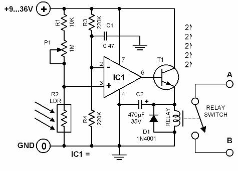
The brightness of the surrounding light controls the function of this circuit. The light sensor used in this circuit is a light-dependent resistor (LDR). This LDR is connected to the non-inverting input of the 741 op-amp IC. Once the...