
Remote Doorbell Warning Switch
The circuit described utilizes a solenoid-type doorbell switch to activate a remote lamp indicator when the doorbell is pressed. The primary component of the circuit is a relay, which is used to isolate the lamp from the doorbell circuit and prevent any additional load on the doorbell's power source. The relay is typically a single-pole double-throw (SPDT) type, allowing it to control the lamp's power independently of the doorbell.
When the doorbell switch is pressed, it completes a circuit that energizes the relay coil. This action closes the relay contacts, allowing current to flow from the power source to the lamp, which can be located in a different room or area. The relay should be rated appropriately for the lamp's voltage and current to ensure safe operation.
To enhance the circuit's functionality, a diode can be placed in parallel with the relay coil to prevent back EMF from damaging the circuit when the relay is deactivated. The diode should be oriented to allow current to flow in the reverse direction, effectively shunting any voltage spike generated by the coil when the relay opens.
For applications where a visual indication is required without the use of a traditional lamp, an LED can be employed instead. In this case, a current-limiting resistor must be included in series with the LED to prevent excessive current from flowing through it. The resistor value can be calculated based on the forward voltage and current specifications of the LED.
This circuit design offers a practical solution for individuals who may miss the auditory signal of a doorbell, providing a reliable visual cue that can be easily integrated into existing doorbell systems. It is important to ensure that all components are rated for the appropriate voltage and current levels to maintain safety and functionality.This circuit will light a lamp at a remote location when the doorbell switch is pressed. This circuit should only be used with the solenoid type doorbells, the electronic type that play tunes will not work here. It is quite easy to miss the sound of a doorbell if you are watching TV , this circuit gets round the problem by providing a visual indication.
As an alternative, a LED could also be used. You could just parallel a lamp across the doorbell, but this would mean extra drain from the doorbell batteries or transformer. 🔗 External reference
Related Circuits
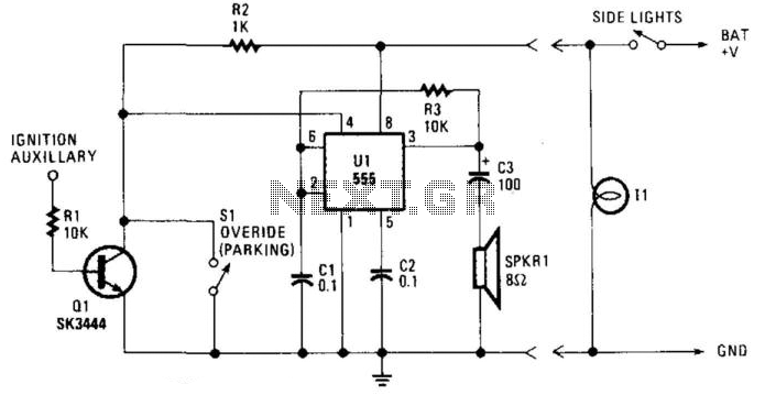
The circuit derives its power from the car's side lights, preventing oscillation unless the lights are on. The reset pin on the 555 timer connects to transistor Q1. The base of Q1 is linked through resistor R1 to the...
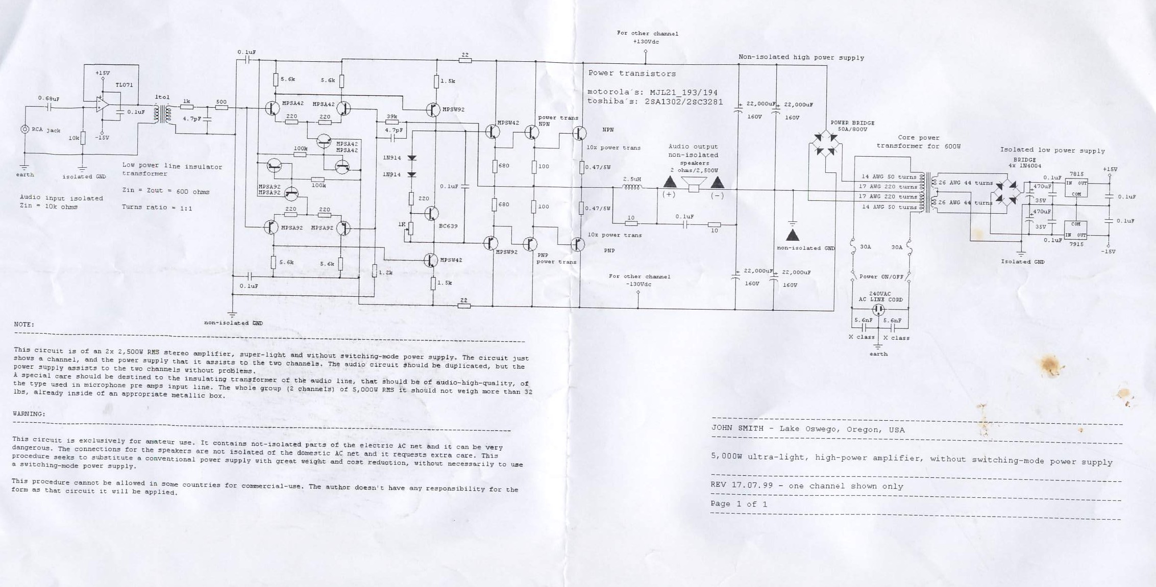
This circuit is for a 2x2, 500W RMS stereo amplifier that is super-light and does not utilize a switching-mode power supply. The circuit diagram displays only one channel, while the power supply is designed to support both channels. The...
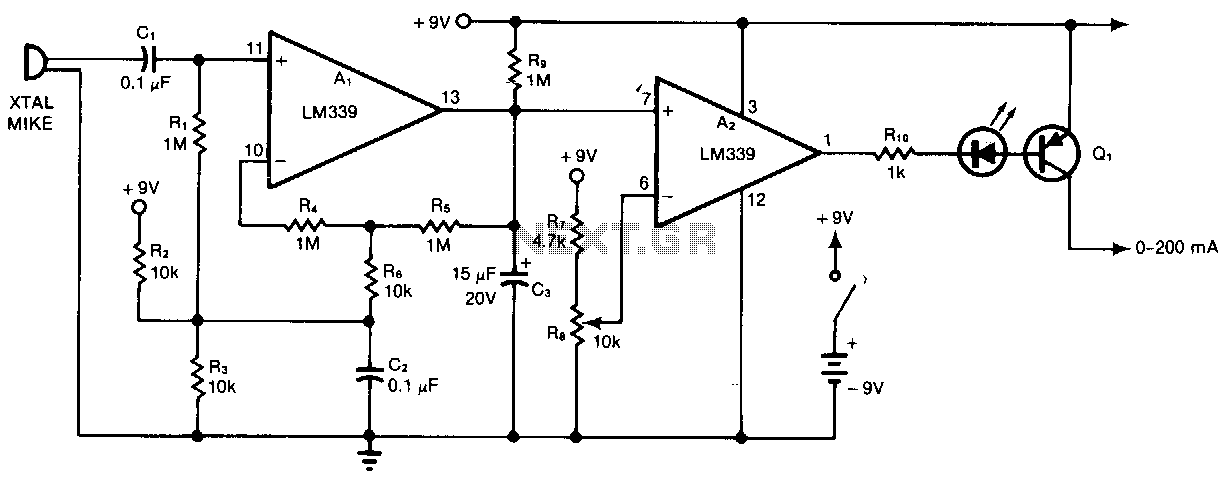
Al and A2 are two sections of a quad comparator. The first section, Al, functions as an amplifier and detector. Resistors R5 and R6 set the gain at 100; the output of Al is an open collector to negative-peak-rectify...

This article discusses a simple 5-channel radio remote control circuit utilizing the TX-2B and RX-2B integrated circuits from Silan Semiconductors. The TX-2B/RX-2B is a remote encoder-decoder pair suitable for remote control applications. It features five channels, a wide operating...

Instructions for creating a Clap-Clap On/Clap-Clap Off switch circuit. This guide provides the necessary information for constructing a clap-activated switch. The Clap-Clap switch circuit is an innovative design that utilizes sound activation to control electronic devices. The primary components of...
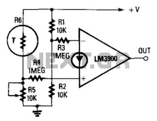
The output becomes high when a predetermined temperature is surpassed. A fixed half-supply reference voltage provides a reference current to the inverting input, while a variable current is supplied to the non-inverting input. Resistor R6 functions as a negative-temperature-coefficient...