
Field-strength meters
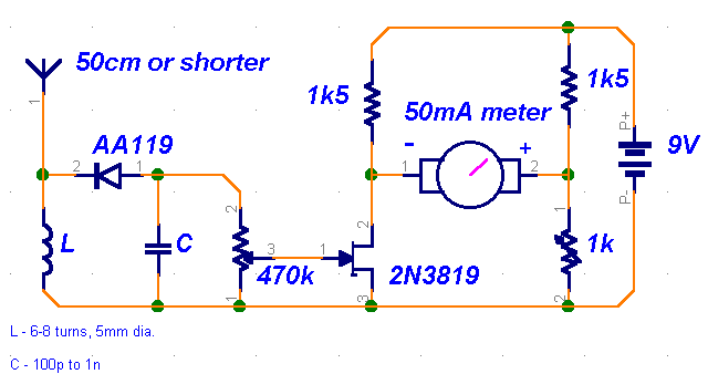
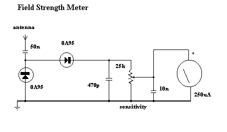
The circuit design begins with a crystal receiver, which is an essential component for detecting radio frequency signals. The choice of a germanium diode, like the 1N34 or AA119, is critical due to its ability to rectify low-level signals effectively. The inductor and capacitor form a resonant circuit that defines the frequency of operation. The coil's construction, with a diameter of 5 mm and 6 to 8 turns of 1 mm thick wire, is designed to optimize the reception of FM and VHF signals. Adjusting the spacing of the coil turns allows for fine-tuning of the frequency, providing flexibility in the circuit's operation.
The capacitor, while less critical, should ideally be around 100 pF to ensure proper tuning and performance. The second stage incorporates the 2N3819 JFET, known for its high input impedance, which is vital for minimizing loading effects on the previous stage. The inclusion of a 470 kΩ potentiometer facilitates sensitivity adjustments, allowing the user to optimize the circuit's response to incoming signals.
A trimmer capacitor is also integrated into the design to enable precise zeroing of the meter, ensuring accurate readings. The use of an ammeter, preferably one rated for 50 mA or slightly smaller, allows for practical measurement of the output signal strength. However, it is important to note that the performance of this simple detector-based meter is limited, and it is primarily suited for basic evaluations of transmitter power levels.
The field-strength meter serves a dual purpose: it aids in determining when a transmitter is functioning at optimal power and is instrumental in aligning various stages of the circuit. This is particularly beneficial when working with a 4W transmitter or when testing different antenna configurations, as it provides feedback on the effectiveness of the setup. Overall, this circuit represents a practical and efficient approach to receiving and measuring radio frequency signals.This is a very straightforward circuit. The first stage acts as a crystal receiver. Use a germanium detector diode (like 1N34, but AA119 is much more common in Europe), a silicon one won`t do. The frequency is determined by L and C. For the FM band and VHF, wind a coil 5mm in diameter, 6-8 turns of coated wire 1mm thick. You can always vary the fr equency by spacing the turns a bit looser or tighter. C is much less critical. Something around 100p is preferable, though. The second stage is based around the versatile 2N3819 JFET high-impedance amplifier. With the 470k potentiometer you can adjust sensitivity of the circuit. The trimmer is used to zero the meter. Use any old 50mA or slightly smaller ammeter from the junk box. You can`t expect great performance from such a simple detector-based meter. Sensitivity is just adequate enough to get a basic idea of the power that your transmitter is capable of. Use the field-strength meter to find out when a transmitter is operating at optimal power. It can be very handy when aligning stages (like in case of the 4W transmitter) or experimenting with different antennas.
🔗 External reference
Related Circuits
Chen is in the operational amplifier circuit, utilizing a feedback loop with input resistance that determines the current roll-off. The FET drain current is controlled by the determination circuit, which provides the necessary voltage. The output constitutes a fake...
Because it uses few parts, a printed circuit board is not necessary; components can simply be soldered to one another. However, a box is desirable for operating convenience. The case and aerial from a discarded toy walkie-talkie was used...
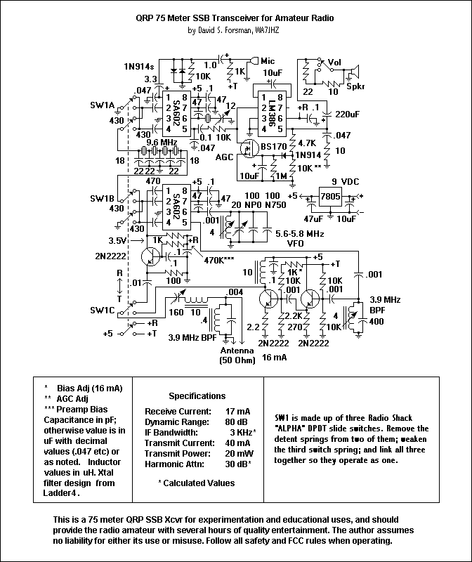
In general, the transceiver switches the 4-element 1500 ohm xtal BPF ends between the inputs and outputs of the two SA602s to reverse the signal flow for R/T operation. Since no IF amplifier is used in the design, 20...
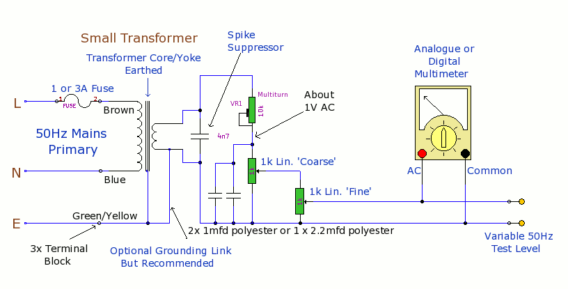
The purpose of this prototype unit is to eliminate the need for an oscillator. It provides a mains-derived and fully variable 50 Hz AC voltage, adjustable down to millivolts for comparison and accuracy testing of two or more parallel-connected...
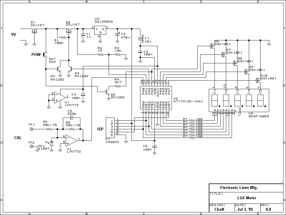
Lux meter circuit using an Atmel ATtiny26-16 microcontroller, which displays lux values on an LED display. The circuit utilizes 2SK1061 MOSFETs for driving the LEDs. The lux meter circuit operates by measuring ambient light levels and converting these measurements into...
Early transmitters using LC oscillators experience significant frequency drift. The introduction of Surface Acoustic Wave (SAW) devices addresses this issue, providing substantial frequency stability comparable to crystals. These devices can achieve fundamental frequencies in the hundreds of megahertz or...