
car parking sensor circuit using infra
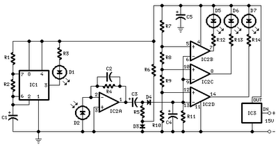
The described circuit utilizes infrared (IR) LEDs for transmission and reception, which can be applied in various sensing applications. The performance of the circuit is influenced by the type of infrared LEDs selected, with specific attention given to their wavelength and output power. The sensitivity of the system is notably impacted by the color of the reflecting surface; lighter surfaces tend to enhance sensitivity, while darker surfaces, particularly black, significantly diminish it.
The integration of an infrared photodiode (D2) with an optical sunlight filter is crucial for ensuring reliable operation in environments with ambient light. The design recommendation indicates that this photodiode should be housed in a black plastic casing to minimize interference from external light sources. The photodiode's sensitivity is maximized when the curved surface is oriented correctly, as it is designed to capture more incoming infrared light effectively.
The circuit should be compact, with all components, including the infrared LEDs, housed together to reduce the influence of external factors and maintain signal integrity. The signaling LEDs, which indicate the status of the system, should be placed at an elevated position for optimal visibility, ensuring that they can be easily seen by the operator, such as a car driver.
For calibration, the procedure involves adjusting the distance between the transmitting LED (D1) and the photodiode (D2). The optimal distance is critical for achieving the desired response from the signaling LED (D5). This adjustment should be performed carefully, starting from a close proximity and gradually increasing the distance until D5 turns off, indicating the effective range has been surpassed. Typically, the ideal operational distance between D1 and D2 is maintained within 1.5 to 3 cm, ensuring reliable detection and signaling for the intended applications.
This circuit design offers flexibility for various applications, including liquid level detection and proximity sensing, making it a versatile choice for engineers and developers in the field of electronics.All distances mentioned before can vary, depending on infra-red transmitting and receiving LEDs used and are mostly affected by the color of the reflecting surface. Black surfaces lower greatly the device sensitivity. Obviously, you can use this circuit in other applications like liquids level detection, proximity devices etc.
The infra-red Photo Diode D2, should be of the type incorporating an optical sunlight filter: these components appear in black plastic cases. Some of them resemble TO92 transistors: in this case, please note that the sensitive surface is the curved, not the flat one.
It is wiser to place all the circuitry near the infra-red LEDs in a small box. The 3 signaling LEDs can be placed far from the main box at an height making them well visible by the car driver. The best setup is obtained bringing D2 nearer to D1 (without a reflecting object) until D5 illuminates; then moving it a bit until D5 is clearly off.
Usually D1-D2 optimum distance lies in the range 1. 5-3 cm. 🔗 External reference
Related Circuits
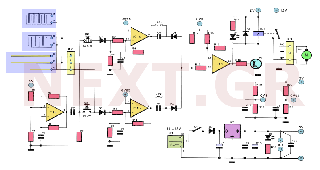
Often, for various reasons, individuals forget or are unable to water the plants in their homes. Many humidity sensor units merely alert users with a beeping sound or a flashing light when the pot requires watering. However, what if...
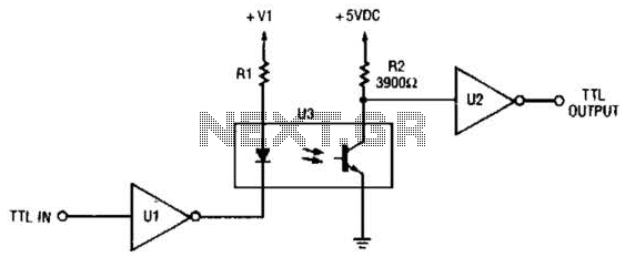
This circuit is a TTL-to-TTL isolator circuit. The driver circuit is an open-collector TTL inverter (U1). When the input is high, the output of the inverter is low. Thus, when the input is high, the output of U1 grounds...
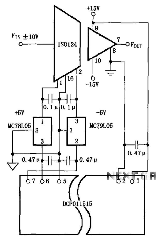
The circuit depicted in the figure includes the ISO124 and MC78L05 components, along with an external regulator, MC79L05, and the DCP011515, which collectively enhance the power supply rejection ratio (PSR) of the circuit. The input signal, VIN (maximum swing...
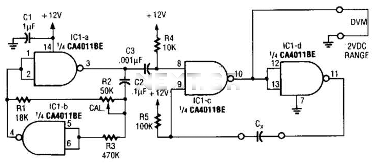
This circuit is designed for capacitor matching applications. The DC output voltage is directly related to the capacitance values of capacitor Cx. The specified circuit values are intended for capacitors in the 0.01 microfarad range; however, they can be...
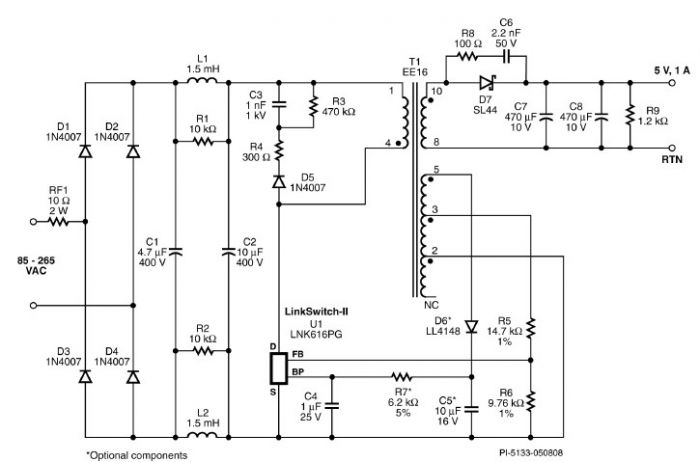
A very simple 5-volt constant voltage, constant current (CV/CC) universal-input power supply for cell phone or similar charger applications can be designed using the LNK616PG product from the LinkSwitch-II family. This low-cost charger adapter accepts a wide range of...
The paraphase configuration is noteworthy for its ability to adjust either treble or bass, but not both simultaneously. The adjustments made to the tone controls directly influence the slope of the frequency response and the extent of bass and...