
2Y-2Y connection two-speed motor contactor control circuit
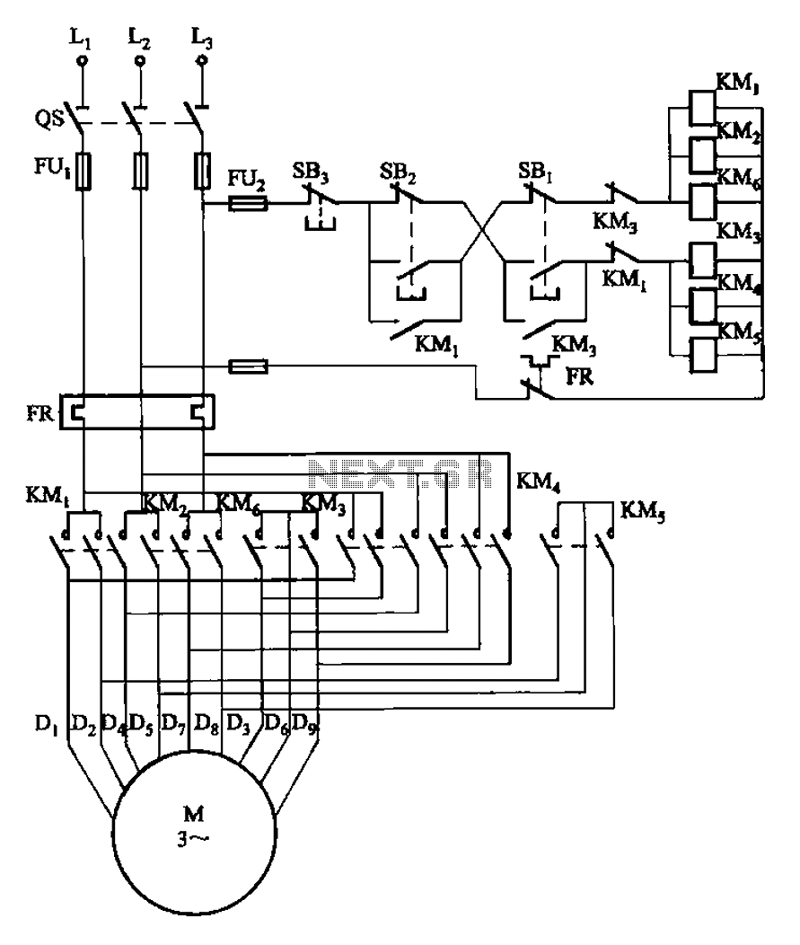
The circuit design depicted in Figure 3-107 integrates two operational modes controlled by distinct buttons: SBi for low-speed operation and SB2 for high-speed operation. The functionality of this circuit can be understood by examining the role of each component and the overall configuration.
In this schematic, the low-speed button (SBi) is typically connected to a resistor-capacitor (RC) network, which may introduce a delay or limit the current flow, thereby reducing the operational speed of the connected device. This ensures that the device operates smoothly at lower speeds, which may be necessary for applications requiring precision or gradual acceleration.
Conversely, the high-speed button (SB2) is designed to bypass the RC network or provide a direct connection to the power supply, allowing the device to operate at its maximum speed. This configuration is beneficial for applications where rapid response times are critical, such as in motor control or high-speed data transmission.
The circuit may also include additional components such as diodes for protection against reverse polarity, transistors for switching, and indicators (LEDs) to provide visual feedback on the operational mode selected. The design should ensure that the transition between low-speed and high-speed modes is seamless and that the circuit can handle the different current demands without overheating or failing.
Overall, the schematic serves as a versatile solution for applications requiring variable speed control, effectively allowing users to select the desired operational mode based on their specific requirements. Circuit shown in Figure 3-107. Figure, SBi is running at low speed button, SB2 for the high-speed operation button.
Related Circuits
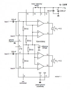
A 2x22 W car audio amplifier circuit utilizes the TDA1558, a monolithic integrated class-B output power amplifier that includes four 11 W single-ended amplifiers or two 22 W bridge-tied load (BTL) amplifiers. The TDA1558 is designed to drive speakers in...
A collection of touch switch circuits is presented. A touch switch is an electronic device that allows control of a circuit simply by touching a sensor. The circuit diagram illustrates a simple design that utilizes only eight components. The...
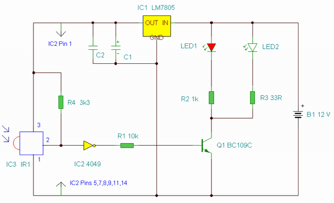
This is an enhanced infrared (IR) remote control extender circuit. It features high noise immunity, resistance to ambient and reflected light, and an increased operational range. The improved IR remote control extender circuit is designed to extend the range of...
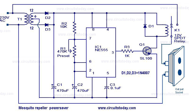
The circuit diagram of a mosquito repellent power saver circuit is provided along with a detailed explanation. The mosquito repellent power saver circuit is designed to efficiently operate a mosquito repellent device while minimizing energy consumption. This circuit typically integrates...
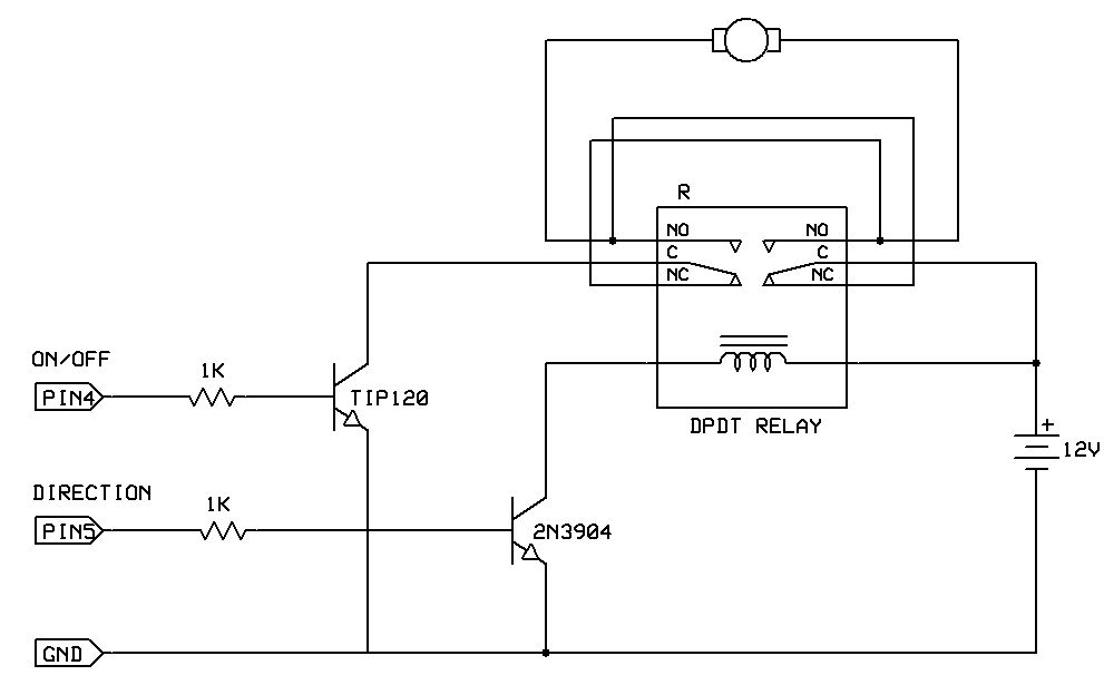
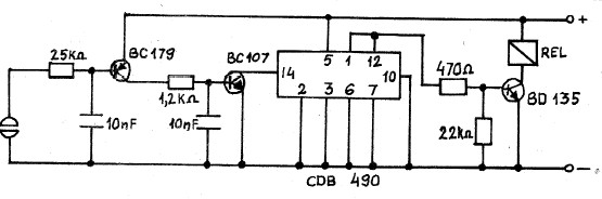
One of the simplest methods to enable a motor to rotate in both directions is by utilizing a double-pole, double-throw (DPDT) relay. This setup requires two transistors and two Stamp pins: one for on/off control and the other for...
The foot 13 between valve value 1 and valve value 2 will draw the transistor base current. If the relay releases, after a recovery time of 0.5 seconds, pressing the key will initiate the switching process again. The timer...
Warning: include(partials/cookie-banner.php): Failed to open stream: Permission denied in /var/www/html/nextgr/view-circuit.php on line 713
Warning: include(): Failed opening 'partials/cookie-banner.php' for inclusion (include_path='.:/usr/share/php') in /var/www/html/nextgr/view-circuit.php on line 713