
Analog Tachometer Readout
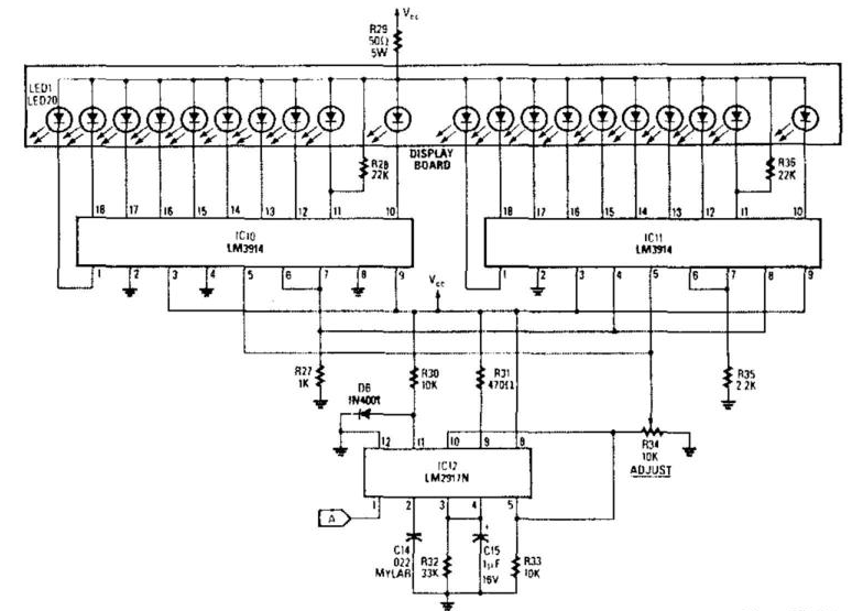
The analog display circuit is designed to visualize engine RPM through a series of illuminated LEDs, providing real-time feedback to the operator. The frequency-to-voltage converter (IC12) takes the input frequency from the engine's tachometer signal and converts it into a proportional voltage. This conversion is crucial as it allows for a straightforward interpretation of engine speed in a visual format.
The output voltage from IC12 is fed into the bar-graph segment drivers, IC10 and IC11, which manage the illumination of the LED segments. These drivers are responsible for controlling the brightness and activation of the LEDs based on the voltage levels provided by IC12. Each segment corresponds to a specific range of RPM, allowing the operator to easily gauge engine performance.
R34 serves as the calibration adjustment resistor, enabling fine-tuning of the system to ensure accurate LED activation at the specified RPM thresholds. By adjusting R34, the system can be calibrated to light the first LED at an engine RPM of 5,000 to 7,000, marking the critical redline value. This feature is essential for performance monitoring, as it helps prevent engine over-revving and potential damage.
Overall, this analog display circuit provides a reliable means of monitoring engine RPM, utilizing a combination of frequency-to-voltage conversion and LED visualization to enhance user experience and safety.The analog display consists of a frequency/voltage converter (IC12) and bar-graph segment drivers IC10 and IC11. R34 is the calibration adjustment and is set so that an engine rpm of 5 000 to 7000 rpm lights the first LED (redline value)
🔗 External reference
Related Circuits
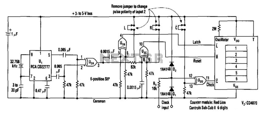
This counter facilitates the direct readout of frequency-generating equipment by incorporating a 1-Hz time base to latch, reset, and condition the count signal. The design allows for the selection of either polarity. By differentiating, inverting, and ORing the clock...
This circuit is designed to drive a total of 42 LEDs, assuming a forward voltage of approximately 2.2V per LED and a forward current of around 21mA for adequate brightness. If the specifications of the LEDs differ significantly, modifications...
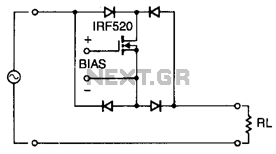
Utilizing four diodes in an array enables the use of a single MOSPOWER transistor for analog switching. The current flow is managed by maintaining the source-base connection of the MOSFET towards the load. It is essential to select diodes...
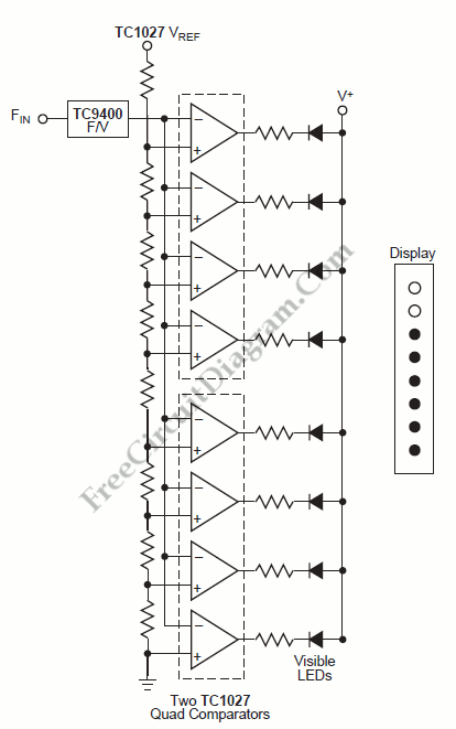
A tachometer can be constructed using the TC9400 in frequency-to-voltage (F/V) mode to convert frequency information (RPM) into a linearly proportional voltage. This voltage can then be compared to one of several comparators (in this example, using eight). The...
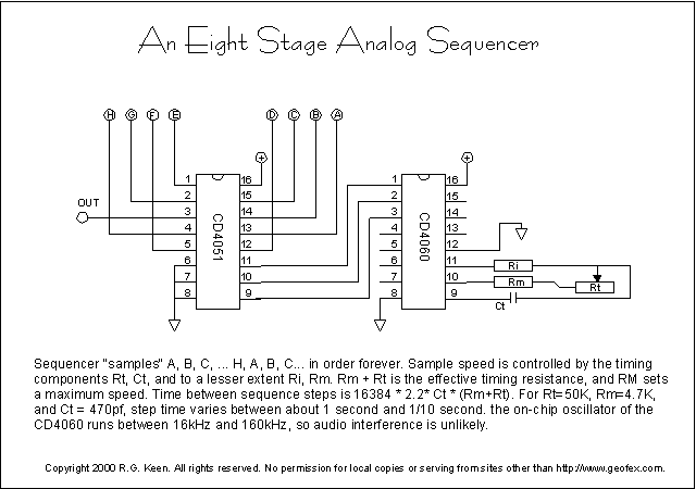
The CD4060 is a CMOS 14-stage binary counter with an internal oscillator on chip. The oscillator is controlled by the resistors and capacitor tied to the timing pins, 9-11. This oscillator runs the binary counter, and the various outputs...
An analog electronic clock that utilizes a trigger signal for operation. An analog electronic clock typically employs a trigger signal to manage its timekeeping functions. The clock's primary components include a quartz crystal oscillator, which provides a stable frequency reference,...