
8 stages LFO analogue sequencer

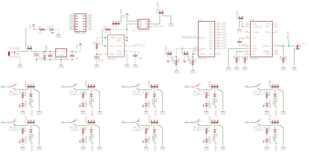
The CD4060 integrated circuit serves as a versatile component in digital electronics, functioning as a 14-stage binary counter and oscillator. The internal oscillator is adjustable through external resistors and capacitors connected to pins 9-11, which determine the frequency of oscillation. This frequency can be varied significantly, and the outputs on pins 1, 2, and 3 provide scaled frequencies of the oscillator, specifically at 1/16384 of the oscillator frequency. The configuration allows for a frequency range from 1 Hz to 10 Hz when the oscillator operates between 16384 Hz and 163840 Hz.
The outputs from the CD4060 are directed to the CD4051, which is an analog multiplexer that functions as a one-of-eight selector switch. The CD4051 connects one of its eight inputs (labeled A through H) to a single output pin (pin 3) based on the binary count from the CD4060. This arrangement allows for sequential selection of the inputs, creating a low-frequency oscillator (LFO) output that can represent eight distinct voltage levels, each adjustable via connected potentiometers.
The design incorporates NPN transistors for signal modulation. The base current of the NPN transistor is controlled through high-value mixing resistors (typically 100K ohms or greater), which act as current sources. This configuration minimizes the impact of voltage variations while allowing the transistor to amplify the modulated signal. An electrolytic capacitor is utilized to block DC offset voltages from affecting the circuit, while a capacitor between the base and emitter serves to smooth out rapid voltage changes, ensuring stable operation.
In an alternative configuration, a P-channel JFET can be used as a variable resistor. When the gate voltage is more positive than the source, the JFET behaves as a resistor, allowing for control over the resistance based on the voltage applied to the gate. This approach provides flexibility in controlling the output signal, with the necessity of a pulldown resistor to maintain proper voltage levels and prevent negative voltages at the gate.
Overall, the combination of the CD4060 and CD4051, along with NPN transistors or P-channel JFETs, creates a robust electronic circuit capable of producing varied LFO outputs suitable for applications such as audio modulation and signal processing.The CD4060 is a CMOS 14-stage binary counter with an internal oscillator on chip. The oscillator is controlled by the resistors and capacitor tied to the timing pins, 9-11. This oscillator runs the binary counter, and the various outputs count at the oscillator speed. In particular, pins 1, 2, and 3 count at 1/16384 th of the oscillator frequency. If we set the main oscillator to run from 16384 Hz to 163840Hz, then outputs 1,2 and 3 count at from 1 Hz to 10 Hz. The outputs at pins 1-3 are supplied to the selector inputs of the CD4051. The 4051 is a one-of-eight analog selector switch. This is like a single pole, eight throw switch that connects one of eight positions to a single output pin. As the counting inputs change, input A, B, C, ... H are selected in turn and connected to the output on pin 3. Once H is reached, the cycle starts over at A. The inputs to the selector chip can be any voltage within the range of the chip's positive supply pin (shown as a plus sign with a circle around it) to its most negative supply pin, shown as ground.
We could connect eight potentiometers to those inputs, with the potentiometers strung between the + supply and ground. If we did that, we could adjust the voltage for each step independently, and the sequencer would select each of those in turn.
The LFO output could be any of eight different values, depending only on the settings of the eight pots. There is a commercial device that does a similar operation, although I have no idea if it's implemented in the same way.
This task would be almost impossible to do with any reasonable number of opamps. To control the NPN transistor, all we need to do is to note that the transistor really doesn't care what voltage is there, it only cares about the current into its base. We can simply make the Rm mixing resistors be large, maybe 100K and up, and the resistors themselves make an effective "current source" into the NPN transistor's base.
If the transistor's collector resistance is connected directly to the signal lines, we need to do some housekeeping to keep things nice. A big electrolytic capacitor as shown will keep the inherent offset voltage of the bipolar transistor from being transmitted into the circuit; likewise, we probably want a capacitor of some kind from the base to emitter to slow down the very fast jumps of voltage that digital LFO's feed to the transistor base.
The transistor is, after all, still an amplifier, and it will amplify those steps as well! Slow it down a bit. With mixing resistors in the 100K and up class and a 2N5088, circuit A can be used to operate the Seamoon and Dr. Q. wah filters, and the single-resistor-to-ground wahs as noted in The Technology of Wah Pedals here at GEO.
Another way to get a variable resistor to ground is shown in B. A P-channel JFET acts like a variable resistor when its gate is more positive than its source. We've shown the source grounded, and the Vc control voltage applied to the gate. Since Vc from our digital LFO's can go from ground to some positive voltage easily, this connection is also a natural. Most JFET do not need a range of 0V to 9V of Vgs to go from fully on to fully off, so in this case, we will likely need a pulldown resistor to decrease the size of the LFO output and make sure it never goes more negative than ground.
A P-Channel JFET is fully on when its gate is the same voltage as its source, and has a higher and higher resistance as its gate gets more positive; this is the reverse of the NPN transistor, so a larger Vc turns a P-channel JFET more OFF (higher resistance) while a larger Vc turns an NPN transistor more ON (lower resistance). 🔗 External reference
Related Circuits
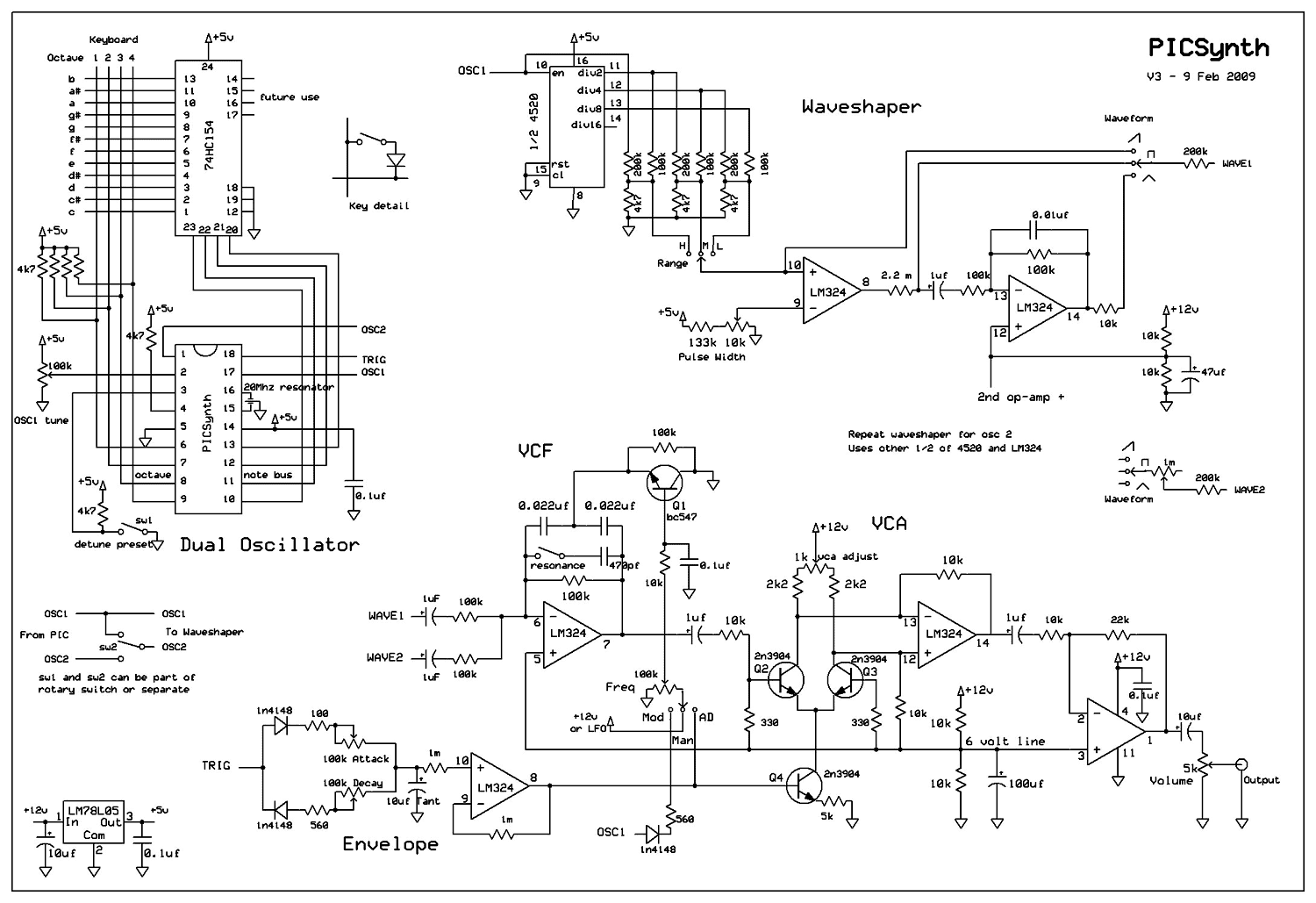
A real analog synthesizer to build using easy to get components, capable of a wide range of sounds. The two oscillators can be detuned for that classic synth sound. Dual oscillator mono synth. Really easy to build using just...

The drawing below illustrates a multistage light sequencer using discrete parts and no integrated circuits. The idea is not new and I hear a similar circuit was developed about 40 years ago using germanium transistors. The idea is to...
This analog sequencer was designed with cooperative play in mind. It can function as a standalone instrument or be linked with other sequencers operating at the same clock speed. Mark Kleback and another collaborator were independently developing sequencers based...
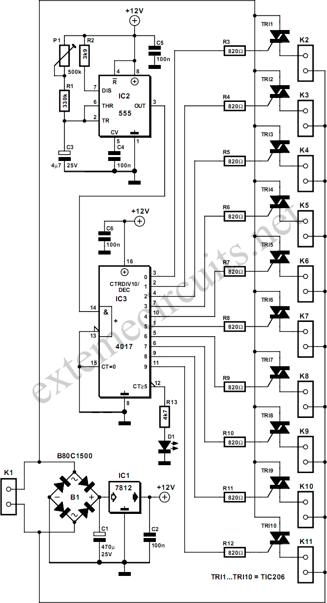
This circuit utilizes a 555 timer to control a 4017 decade counter. The outputs from the counter are used to drive transistor relay drivers. The duration for which the lights remain "on" can be adjusted by modifying the connections...
This circuit resembles an LED clock but utilizes 12 neon indicator lamps in place of LEDs. It operates on two high-capacity nickel-cadmium cells (2.5 volts), providing power for several weeks. A small switching power supply generates the high voltage...
Dedicated model rail enthusiasts using sophisticated train and point controllers often encounter the issue that as their layouts expand and become more complex, the transformer supplying power to the points does not provide sufficient current to switch multiple points...