
led lights using analog flip flop circuit diagram

The LED driving circuit functions by providing the necessary current and voltage to illuminate the LEDs effectively. Each LED in the series configuration requires a specific forward voltage to operate correctly, and the total voltage drop across all 42 LEDs must be accounted for in the power supply design. For 42 LEDs at 2.2V each, the total forward voltage required is approximately 92.4V (42 x 2.2V).
To achieve the desired forward current of 21mA, a current-limiting resistor should be included in the circuit. This resistor is essential for preventing excessive current from damaging the LEDs. The value of the resistor can be calculated using Ohm's Law: R = (V_supply - V_total) / I, where V_supply is the voltage from the power source, V_total is the total forward voltage drop across the LEDs, and I is the desired current (21mA in this case).
The 2N3904 transistor acts as a switch to control the flow of current to the LEDs. When a suitable base current is applied to the transistor, it allows current to flow from the collector to the emitter, thus powering the LEDs. The base resistor should be calculated to ensure that sufficient base current is provided to saturate the transistor, allowing it to operate efficiently in the switching mode.
In summary, this circuit design requires careful consideration of the power supply voltage, current-limiting resistors, and the transistor's switching characteristics to ensure reliable operation of the LED array. Adjustments may be necessary based on the specific characteristics of the LEDs used in the application.This will drive a total of 42 LEDs. It is based on the assumption that the forward voltage of your LEDs is ~2. 2V, and that they will be bright enough with a forward current of ~21mA. If yours are a lot different, I will have to modify the design. The 2n3904 is a general purpose NPN audio/switching transistor which should be similar to the one show n in the schematic you posted. 🔗 External reference
Related Circuits
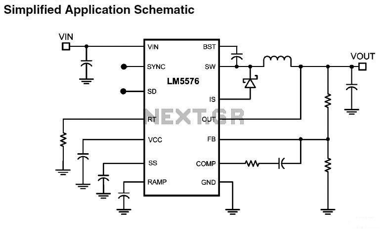
LM5576MHX absolute maximum ratings: (1) VIN to GND: 76V; (2) BST to GND: 90V; (3) PRE to GND: 76V; (4) SW to GND (Steady State): -1.5V; (5) BST to VCC: 76V; (6) SD, VCC to GND: 14V; (7) BST...
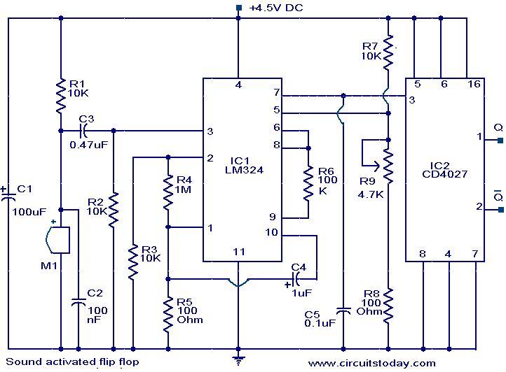
This circuit allows the output pins of a Flip Flop IC to be toggled using sound. A condenser microphone captures the sound, and the first two operational amplifiers in the LM324 IC amplify the signal. The third operational amplifier...
The simple mixer schematic is based on the common base principle, where input voltages are transformed into alternating currents that are summed to form the output. The simple mixer circuit utilizes the common base configuration of a transistor, which is...
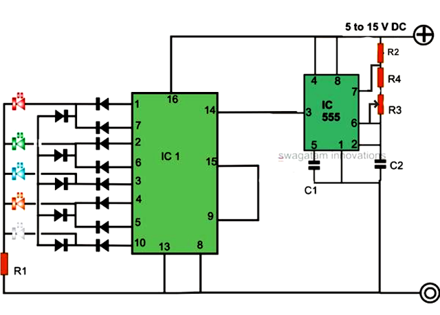
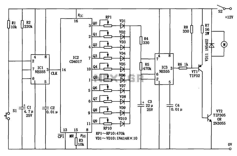
An LED light chaser circuit is an electronic configuration designed to illuminate a group of LEDs in a predetermined sequence. A commonly used integrated circuit (IC) for creating this type of LED sequencer circuit is the 4017. This IC...
The circuit for a car wiper speed controller allows for adjustable wiper speed, ranging from one to ten cycles per second. This feature enables flexibility in operation and contributes to energy efficiency. The car wiper speed controller circuit typically employs...
The circuit receives its input from the zero-crossing detector, which generates a 0-to-1-to-0 pulse to set the R-S flip-flop and activate the ramp circuit (A to Ramp) to initiate the timing ramp ascent. The described circuit operates by utilizing a...