
Analogue Sound Preasure dB-Meter Circuit
To measure sound in dBA, a quality microphone is essential, ideally a capacitive type. The microphone connects to a preamplifier, followed by a filter with an A characteristic curve before reaching the amplifier. This setup forms an alternating current measuring circuit with dB readings. The instrument operates within a range of 50dB to 110dB, focusing on higher levels.
The circuit can incorporate a Philips LBC1055/00 microphone, which is a capacitive microphone with a built-in FET amplifier, providing linear response from 100Hz to 14KHz and capable of handling sound levels up to 134dB without distortion. The microphone's FET is powered through resistors and capacitors, and the signal is amplified by transistors T1 and T2, achieving approximately 20 times amplification based on resistor ratios. The input impedance is determined by R1, which is tailored for the specific microphone used.
The signal then passes through transistor T3 to the A-weighting filter formed by resistors and capacitors, approximating the A-curve. The final output connects to a standard measuring circuit for 1mA moving coil instruments, with protective diode D1 preventing damage from excessive currents.
Measurement range selection is facilitated by switch S1, with voltage from the resistor divider R14-R18 corresponding to the current through the instrument. A moving coil instrument rated for 1mA with high vibration damping is utilized. A suitable scale can be printed based on the circuit configuration.
The printed circuit board (PCB) design accommodates the majority of components, ensuring a compact layout.
Two adjustments are available within the circuit: one for input voltage offset (P1) and another for instrument calibration (P2). The calibration process involves disconnecting the microphone and shorting R1, then adjusting P1 to achieve a zero reading on the display. Calibration can also be performed using a reference sound source, with specific voltage levels applied to the circuit input for accuracy.
The power supply is chosen to be battery-operated due to low consumption requirements, simplifying the design.
List of Components:
Resistors:
R1 = 2.2kΩ
R2 = 10kΩ
R3 = 47Ω
R4, R11 = 6.8kΩ
R5, R6 = 39kΩ
R7 = 1.2kΩ
RB = 8.2kΩ
R9 = 470Ω
R10, R14 = 680Ω
R12, R13 = 100kΩ
R15 = 220Ω
R16 = 68Ω
R17 = 22Ω
R18 = 10Ω
R19 = 330Ω
P1 = 10kΩ adjustable
P2 = 5kΩ adjustable
Capacitors:
C1, C2 = 2μF / 16V
C3, C4 = 47μF / 16V
C5, C6 = 47nF
C7 = 3.3nF
Semiconductors:
T1 = BC549C
T2 = BC559C
T3 = BC547B
D1-D5 = 1N4148
IC1 = 741
Other:
Electret LBC1055/00 Philips Microphone or similar
M = 1mA movable coil
S1 = Monopolar switch of five positions
S2 = Bipolar switchThe best human ear can capture sounds from 20Hz to 20KHz. These limits are known to be the broadest that can exist. Normally the normal limits range from 100Hz to about 13KHz and depend on the age and health of the individual. We for our measurements and to have a good accuracy we will get the limits of 20Hz to 20KHz. A sound to be heard does not need to be only in the audio frequency range, it must have the appropriate volume at the corresponding frequency.
In order for the two sounds to have the same intensity in our ear, we must in fact practice very different pressures on the ear drum, For 100Hz, we need much more pressure to "listen" to the sound with the same intensity, comparing it to the 1KHz sound. This is because our ear has different sensitivity at different frequencies.
The highest sensitivity is between 500Hz and 5KHz. All this is clearly shown in the following figure.

The lower dashed line shows the hearing limits. Sounds below this level are not heard. From the figure we see the hearing limits at 1000Hz is 0dB while at 50Hz it is 40dB. The curves of the diagram are formed by the sound pressure levels that give our ears the impression of the same intensity at the various frequencies (isotonic).
The curve at the top of the chart is also called "pain thresholds." This does not mean that all the sounds below it are harmless. Our hearing loss can also be at a much lower level if we are exposed to noise for a long time (eg. 100dB for 30 minutes). The only thing that characterizes this curve is that we really have a feeling of pain at these levels, and hearing loss can happen in a very short space of time.
The following figure shows the levels of some dBA sounds.
DBA is a relative size that depends on ear features.

Thus, a "real" 60dB at 100Hz should give the same acoustic intensity as a 50dB at 1KHz. Constructing circuits for comparison with such features is not at all easy. However, according to international standards, such precision is not necessary and the curve of the next compensation graph is enough.

This curve is known by the curve name A.
To measure dBA sounds we have nothing else to do by connecting a microfilter with a characteristic curve A.
Measure sound in dBA
To measure the sound, we need first of all a good microphone with a straightforward feature. A microphone of capacity would be ideal. The microphone follows a preamplifier. Between the preamplifier and the amplifier we place the filter with the characteristic curve A. The output of the filter is connected to the amplifier which together with the bridge and the resistors is an alternating current measuring circuit with reading in dB.
The instrument area is from 50dB to 110dB.
The lower levels are not as interesting as the higher ones.
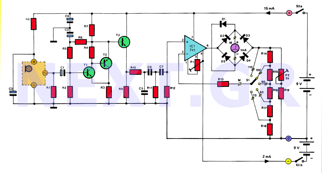
The circuit
As a microphone at the entrance, a Philips LBC1055/00 can be installed. This type is a microphone of capacity, that does not need a high operating voltage. It has a built-in amplifier with FET and its characteristic is linear from 100Hz to 14KHz, it also has the advantage that up to 134dB is not overloaded.
The FET of the microphone is powered by a positive voltage via R8 and C3.
The microphone signal is amplified by T1 and T2. The amplification is about 20 times and depends on the ratio of R7 to R3. The input impedance of the amplifier depends on R1 which, along with amplification, has been calculated for this type of microphone. If another type is used then some changes have to be made.
The signal passes through the T3 whose emitter is connected to the filter A consisting of R10, R11, R12 and C5, C6, C7.
This filter gives a good approximation of the curve. The final step is a standard measuring circuit for 1mA powered moving coil instruments. The IC1 bridge and feedback resistors are a very good AC voltmeter circuit. Diode D1 is used to protect it from large currents.
The measuring range is selected with switch S1. The voltage on the divider R14-R18 is proportional to the current flowing through the instrument. That is, if the feedback is taken from the bottom of the divider, this corresponds to a low input voltage and therefore also to a low scale.
As a moving coil instrument we use one 1mA high vibration damping.
We can use a more sensitive instrument as long as we have a resistance at the same time that it consumes 1mA in full. To print the scale, we can use the following figure.

The PCB design shows the printed circuit board on which almost all the materials are placed.

Adjusting circuit
There are two settings in the circuit.
One with P1 to compensate the input voltage of IC1 to offset and the other to P2 to calibrate the instrument. The first setting is a zeroing which means that if there is no signal at the input, the instrument display must be zero.
The procedure is as follows: Disconnect the microphone because there is a risk of damage, then short circuit R1 and turn the S1 switch to the most sensitive area (70dB). By taking the center P2 at the center we set P1 so that the instrument shows 0.
The best way to calibrate the instrument is to use a standard sound source, or calibrate it with another high-precision sound pressure gauge.
However, since such instruments are scarce, we will describe here another calibration method that is not as good as the previous ones, but gives us a fairly good precision.
Manufacturers of microphones always give a reference level. For LBC1055/00 it can be calculated from the manufacturer's data that for 110dB, the output will be 40mV active value (RMS).
This voltage is applied to the input of the circuit by using an auxiliary device as in the following figure for more precisely.

This device will be connected to R1 while the microphone will be disconnected. If the generator is at 4.04V at 1KHz then the output of the device will have a reference level of 40mV.
With switch S1 in the 110dB scale we set P2 so that the instrument shows 0dB. The power supply of the circuit was chosen by batteries, because the consumption is too small and because a power supply from the grid would make the instrument very difficult.
List of Components
Resistances:
R1 = 2k2
R2 = 10k
R3 = 47Ω
R4, R11 = 6k8
R5, R6 = 39k
R7 = 1k2
RB = 8k2
R9 = 470Ω
R10, R14 = 680Ω
R12, R13 = 100k
R15 = 220Ω
R16 = 68Ω
R17 = 22Ω
R18 = 10Ω
R19 = 330Ω
P1 = 10k adjustable
P2 = 5k adjustable
Capacitors:
C1, C2 = 2μF2 / 16V
C3, C4 = 47μF / 16V
C5, C6 = 47nF
C7 = 3n3
Semiconductors:
T1 = BC549C
T2 = BC559C
T3 = BC547B
D1-D5 = 1N4148
IC1 = 741
Other:
Electret LBC1055/00 Philips Microphone or similar
M = 1mA movable coil
S1 = Monopolar switch of five positions
S2 = Bipolar switch
Related Circuits
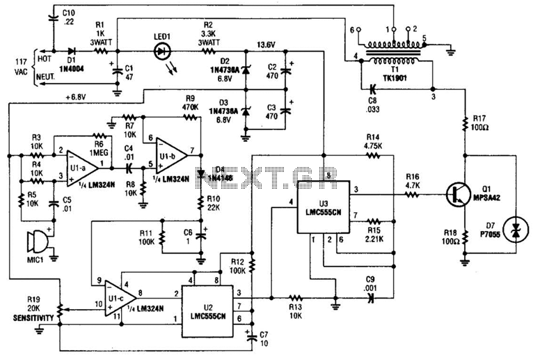
The baby-alert transmitter is constructed using an LM324 quad operational amplifier (U1), two LMC555CM CMOS oscillator/timers (U2 and U3), along with several supporting components. The transmitter activates upon detecting sound at MIC1, emitting a signal. Its operational frequency is...
This is a 35.3 to 10.7 MHz converter circuit. It converts the 35.3 MHz signal coming from a VHF/UHF tuner down to an FM tuner to decode the TV audio in FM. The 35.3 to 10.7 MHz converter circuit is...

This circuit generates a siren sound when switch S1 is pressed. The sound frequency increases as capacitor C1 charges, and when switch S1 is released, the frequency decreases as capacitor C1 discharges. The circuit operates on a simple principle of...
A clock-and-data recovery (CDR) circuit is utilized to recover the clock from a transmitted data stream and re-time that data with the recovered clock. These circuits are generally positioned at the front-end of receiver chips to extract the clock...
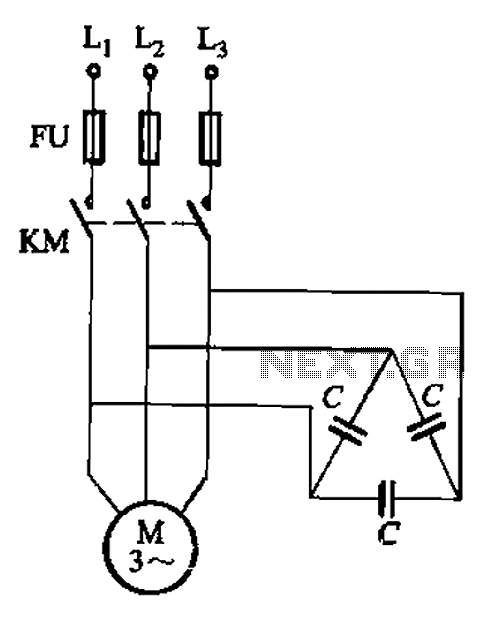
Asynchronous motor reactive power compensation involves directly connecting a capacitor to the stator windings of the asynchronous motor to enhance its power factor. This method is particularly effective for synchronous motors, as it reduces energy consumption related to reactive...
The light from a flashlight is directed at a phototube, which activates a CMOS logic circuit powered by a battery. This circuit controls the switching action to turn the motor of a model train or other electric toys on...