
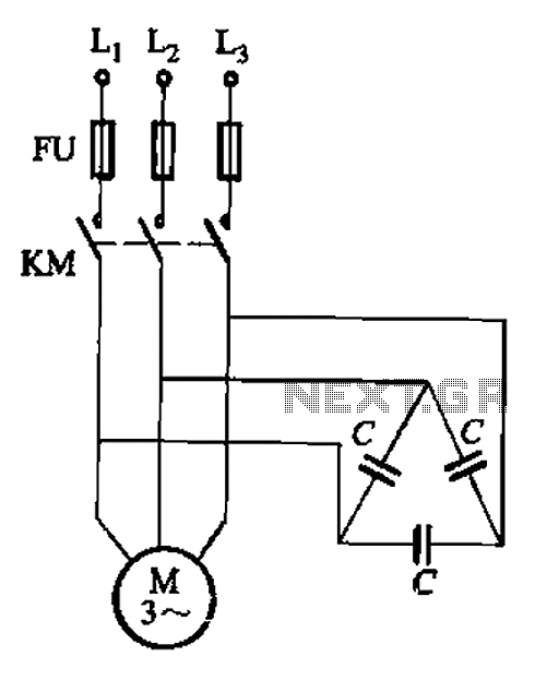
Direct start without power compensation circuit
To implement asynchronous motor reactive power compensation, a capacitor bank is integrated into the motor circuit, ensuring that the reactive power demand is met without drawing excessive power from the supply. This setup not only improves the motor's efficiency but also minimizes losses associated with reactive power. The capacitor bank should be selected based on the motor's specifications, particularly the rated voltage and no-load current, to ensure optimal performance.
In practice, the capacitor bank can be connected in parallel with the motor's stator windings. The selection of capacitance values must be calculated carefully, considering the operational parameters of the motor and the desired power factor correction. The typical range for the reactive power compensation factor (Q) is between 0.7 and 0.9, aligning with the motor's operational characteristics.
Protection measures are essential to safeguard the motor and capacitor bank from voltage spikes and self-excitation conditions. Over-voltage protection devices, such as surge protectors or voltage relays, should be included in the circuit design. Additionally, the use of a frequency-sensitive rheostat can facilitate a smooth start-up of the motor, particularly in applications where load conditions vary significantly.
In summary, the integration of reactive power compensation for asynchronous motors enhances operational efficiency, reduces energy consumption, and requires careful consideration of capacitor selection and protective measures to ensure reliable performance. Asynchronous motor reactive power compensation on the spot, is the capacitor directly connected with the asynchronous motor stator windings connected to increase the power of a synchronous motor is running due to the number, to reduce the energy consumption of a reactive power compensation. It is suitable for large unit capacity (lOkW above), long-running, asynchronous electric power from the distant motives.
Reactive Power Compensation for asynchronous motor must be protected against over-voltage generated and self-motivation. Capacitance compensation should be under selection formula: Q (0- 7 ~ 0 9.) brother Uefo (var) where Ue - rated motor voltage, V; IO- motor no-load current.
A. (1) Direct start without power compensation circuit circuit is shown. The circuit can also be used to start or auto decompression rotor series frequency sensitive rheostat starting in situ reactive power compensation. And directly connected to the capacitor leads to the motor terminals.
Related Circuits
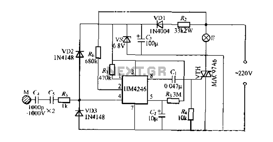
Development and production of a specialized touch dimmer integrated circuit. This circuit features four lighting functions: dark, medium, light, and a touch-sensitive trigger on all four sides. It has low harmonic radiation emission, high touch sensitivity, and stability. It...
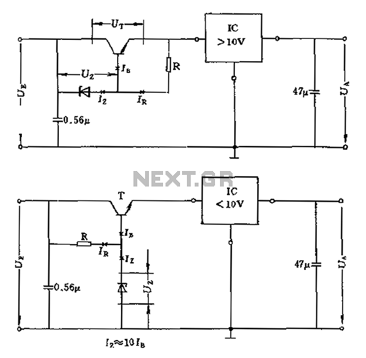
The voltage equation Ue = Ut + Ur + Ua indicates that the transistor voltage Ut will determine the maximum output voltage Ua. Additionally, Ur must be 2V. The voltage regulator's voltage value depends on the selection of Uz....
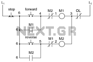
This is the power diagram for motor forward and reverse operation. To change the motor direction, one polarity must be altered, for example, changing R to S. For detailed information, please refer to the following. The described power diagram illustrates...
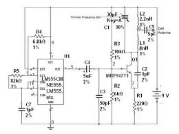
The team is highly interested in the design of a jammer circuit and has begun working on it. However, they are experiencing issues with the circuit, specifically that the signal is not being jammed effectively. The design of a jammer...
This device is a combination digital clock timer and solar panel charge controller designed to maintain a deep cycle battery charged by a solar panel. The timer output controls a 12-volt load for a 32-minute interval each day. The...
This controller is designed primarily for controlling model trains and can deliver approximately 12-15 Volts, though it operates effectively at voltages as low as 3V, including a 6V supply for certain accessories. The maximum output current is theoretically around...
Warning: include(partials/cookie-banner.php): Failed to open stream: Permission denied in /var/www/html/nextgr/view-circuit.php on line 713
Warning: include(): Failed opening 'partials/cookie-banner.php' for inclusion (include_path='.:/usr/share/php') in /var/www/html/nextgr/view-circuit.php on line 713