
Carrier-Current Baby-Alert Transmitter Circuit
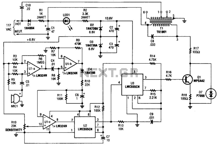
The baby-alert transmitter circuit utilizes the LM324 quad op-amp as the primary processing unit, which provides the necessary amplification and signal conditioning. The circuit is designed to monitor ambient sound levels through a microphone (MIC1). When sound is detected, the op-amp amplifies the audio signal, which is then used to trigger the two LMC555CM timers.
The LMC555CM timers are configured in astable mode to generate a continuous square wave signal at a frequency of approximately 125 kHz. This frequency is chosen to ensure effective transmission and minimal interference with other devices. The output from the timers can be connected to an RF transmitter or directly to an alarm receiver, depending on the application requirements.
Supporting components in the circuit include resistors and capacitors that set the gain of the op-amp and determine the timing characteristics of the 555 timers. Proper selection of these components is essential to ensure reliable operation and optimal performance of the transmitter.
Overall, this baby-alert transmitter circuit serves as an efficient solution for monitoring sound levels in environments such as nurseries, providing a means to alert caregivers when a baby is in distress or making noise. The combination of the LM324 op-amp and LMC555CM timers allows for a compact and effective design that can be integrated into various alarm systems. The baby-alert transmitter is built around an LM324 quad op amp (Ul), two LMC555CM CMOS oscillator/timers (U2 and U3), and a few support components. The transmitter sends a signal on receipt of a sound at MIC1. It has a frequency of around 125 kHz and can be used to trigger an alarm receiver. 🔗 External reference
Related Circuits
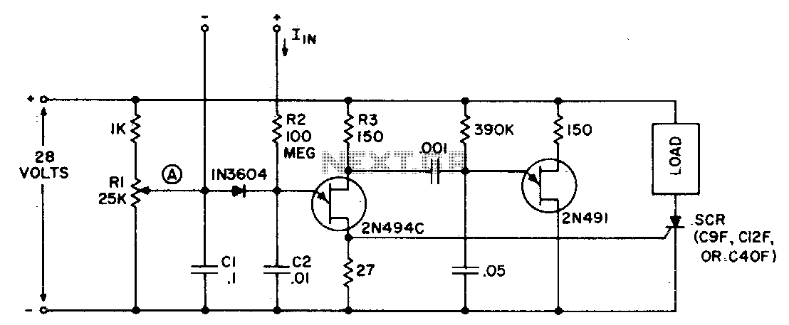
The circuit can function as a sensitive current detector or a voltage detector with high input impedance. Resistor Rl is configured so that the voltage at point (A) is V2 to a few volts below the threshold that activates...

This circuit outputs the maximum or minimum of four input voltages, V1, V2, V3, and V4. Each of these input voltages ranges from 0 to 5 V. The output of the circuit is the maximum of V1, V2, V3,...
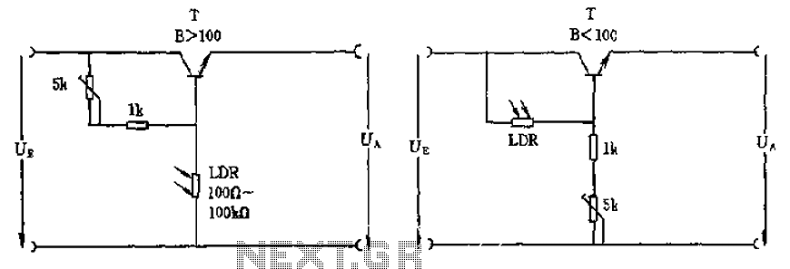
The circuit depicted involves a photoresistor (LDR) connected to a transistor, which operates at either a high or low level based on light conditions. The amplification factor of the transistor is 100, which is adequate for the application. The...

L200 12V Constant Voltage Battery Charger Circuit. This battery charger is based on the L200 regulator IC. The L200 is a five-pin adjustable voltage regulator. The L200 constant voltage battery charger circuit is designed to provide a stable 12V output...
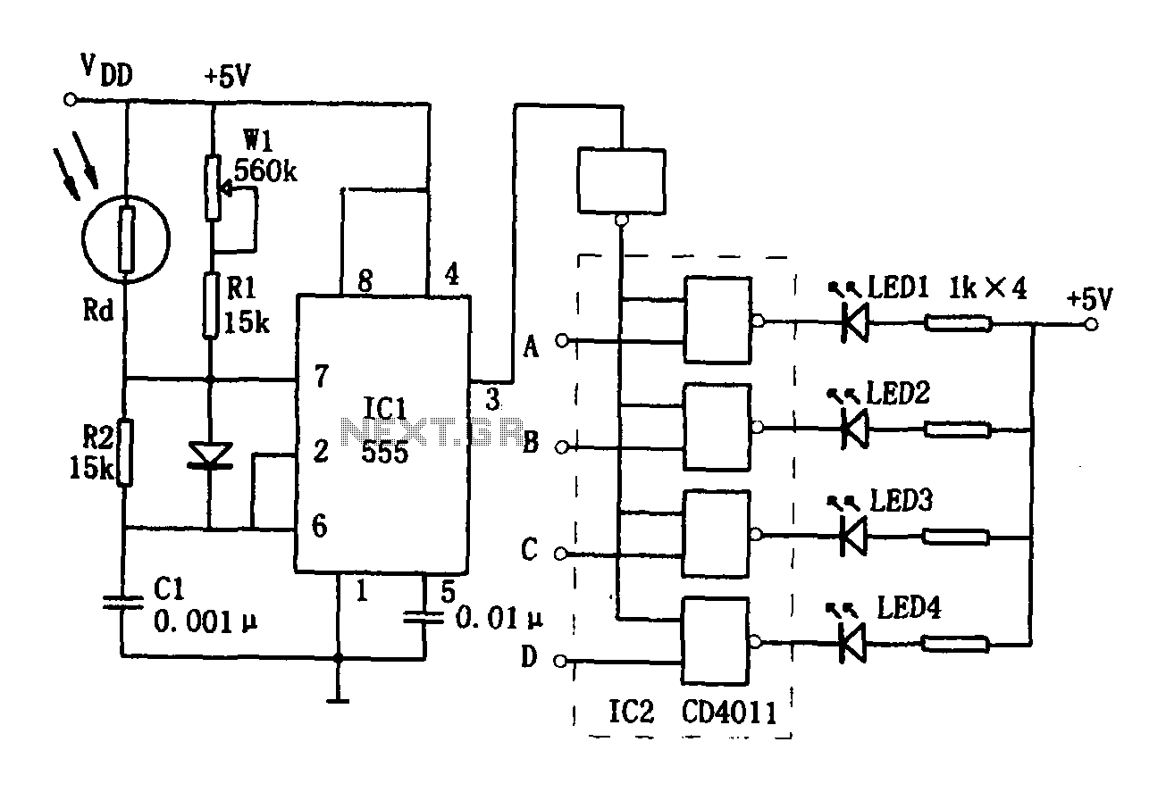
The brightness display circuit consists of a light-sensitive sensor, an oscillation circuit, and an LED display circuit. The light-sensitive sensor is a photosensitive resistor (Rd). The multivibrator is composed of Rd, R1, W1, R2, and C1, along with a...
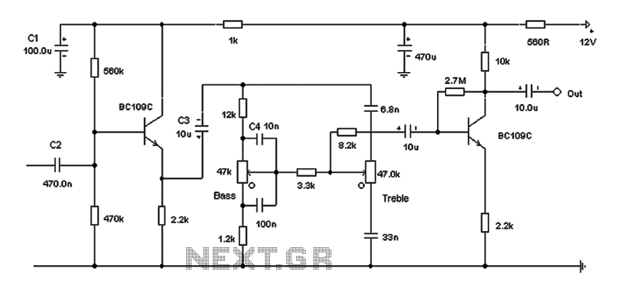
Based on the classic Baxendall tone control circuit, this design offers a maximum cut and boost of approximately 10 dB at 10 kHz and 50 Hz. Since the controls are passive, the final transistor provides a slight boost. The...