
Anatek Lab Supply

The Anatek 50-1S variable power supply circuit is based on a straightforward operational amplifier configuration, which serves as the core of the voltage regulation system. The design incorporates a feedback loop that stabilizes the output voltage while allowing for variable adjustments. The op-amp is configured in a non-inverting mode, where the reference voltage is set using a potentiometer, enabling fine-tuning of the output voltage.
The power supply utilizes a transformer with dual output windings, providing the necessary AC voltage for rectification and regulation. The rectification stage typically employs a bridge rectifier, converting the AC voltage to pulsating DC, which is then smoothed using filter capacitors. The choice of transformer size can vary, as the circuit is adaptable to both larger and smaller transformers, maintaining functionality regardless of the transformer’s power rating.
The circuit board layout is designed with flexibility in mind, allowing for variations in component placement without significant impact on performance. The separate connectors for sense wires ensure accurate voltage sensing at the load, minimizing voltage drop caused by wiring resistance.
The operational amplifier's pin 8 serves as a crucial test point, indicating when the circuit is in current-limited mode. This feature is essential for protecting sensitive loads from excessive current, and the high signal at this pin can be used to drive an LED, providing a visual indication of the current limiting status. Overall, the Anatek 50-1S variable power supply is a robust and versatile design suitable for a range of applications, leveraging common components and straightforward circuit principles.The unit is designed around an ordinary op-amp and easy to obtain parts. Reverse engineered circuit diagram of Anatek 50-1S variable power supply shown below. Circuit board layout does not seem all that critical and as you can see from the schematic that sense wires to the circuit board have their own stake on connectors separate from the output w ires. Although the unit uses a single transformer with two output windings the circuit works equally well using a big transformer and a little transformer. The test point at pin 8 of the op-amp goes high when the variable power supply is operating in current limited mode and it could be used to drive an LED.
🔗 External reference
Related Circuits
The TDA8932B/33(B) can operate with a symmetrical power supply. In this configuration, three half supply voltage buffers are disabled when powered from a symmetrical source. The TDA8932B/33(B) is a high-efficiency Class D audio amplifier designed for various audio applications. Operating...

Miniature isolated AC/DC power supply. This circuit employs a novel method to generate a fully isolated and regulated 5 volts at 30 mA from the 120 VAC power line. It utilizes two tiny SCRs that operate alternately. The miniature isolated...
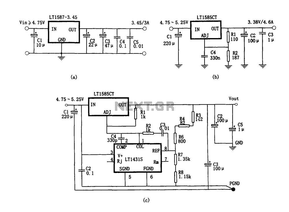
Figure (a) illustrates a microprocessor power supply circuit utilizing the LT1587-3.45. Figure (b) depicts a power supply with an adjustable output voltage constructed using the LT1585. Figure (c) showcases a computer power supply circuit formed with the LT1584 and...
48 V phantom powering has become the standard for professional condenser microphones. The supply (or rather bias) voltage is applied over both wires of the microphone cable. Phantom power is a method used to provide power to condenser microphones through...
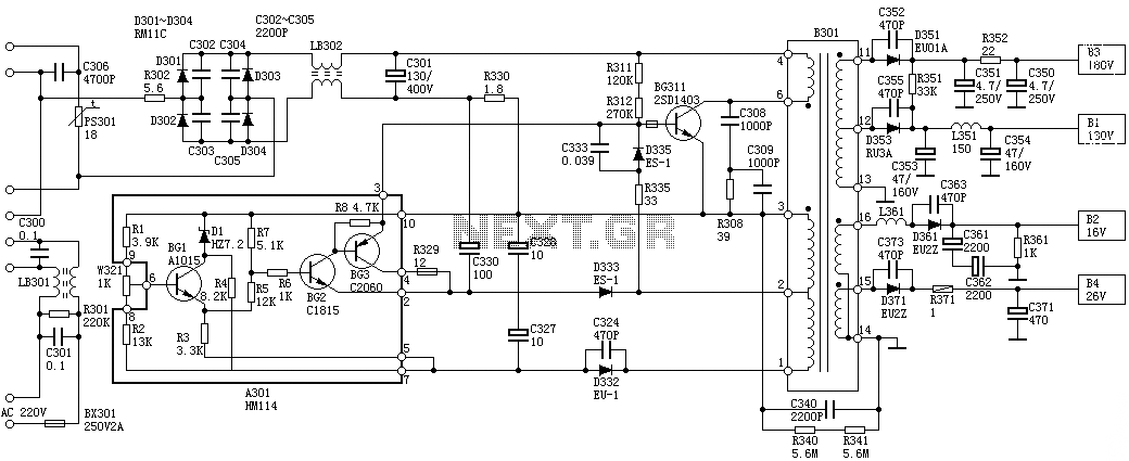
Oscillation: The positive terminal voltage of C310 is approximately 300V. The resistors R311 and R312 are connected to the switch BG311 at the B pole, while the B301 winding via the switching transformer (4) and (6) is connected to...
A high voltage power supply is a valuable source that can be effectively used in various applications, such as biasing gas-discharge tubes and radiation detectors. This type of power supply can also serve as a protective measure, such as...
Warning: include(partials/cookie-banner.php): Failed to open stream: Permission denied in /var/www/html/nextgr/view-circuit.php on line 713
Warning: include(): Failed opening 'partials/cookie-banner.php' for inclusion (include_path='.:/usr/share/php') in /var/www/html/nextgr/view-circuit.php on line 713