
TDA8932B/33(B) Class D Audio Amplifier in Symmetric Supply Single Ended Configuration
The TDA8932B/33(B) is a high-efficiency Class D audio amplifier designed for various audio applications. Operating the amplifier from a symmetrical power supply allows for improved performance by minimizing the distortion and enhancing the audio quality. In this configuration, the amplifier can effectively utilize the positive and negative supply voltages, which can lead to a more balanced output signal.
The diagram referenced indicates that three half supply voltage buffers are disabled. This design choice may be relevant in scenarios where the application does not require the additional buffering, thus allowing for a more straightforward circuit layout and potentially reducing power consumption. The disabling of these buffers can also help in simplifying the design, minimizing component count, and enhancing reliability.
In a typical symmetrical power supply setup, the positive voltage rail and negative voltage rail are equal in magnitude but opposite in polarity. This arrangement allows the amplifier to drive the output signal both above and below ground level, which is essential for producing a full-range audio output without clipping.
Furthermore, when designing the accompanying circuitry, it is crucial to ensure that the power supply is adequately decoupled to avoid noise and maintain signal integrity. Capacitors should be placed near the power pins of the amplifier to filter out high-frequency noise and provide a stable voltage supply during dynamic audio signals.
In summary, utilizing the TDA8932B/33(B) with a symmetrical power supply configuration enhances its operational efficiency while allowing for flexible design choices that can be tailored to specific audio applications.We can also operate TDA8932B/33(B) from a symmetrical supply. On this diagram, three half supply voltage buffers are disabled. When supplied from a symmetrical.. 🔗 External reference
Related Circuits
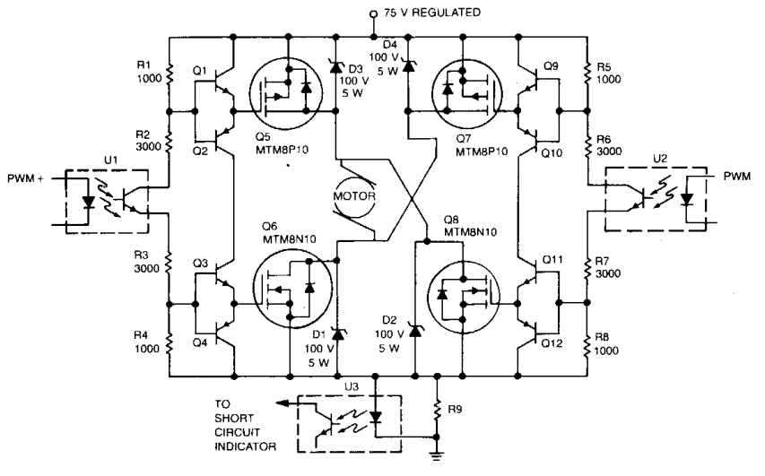
Digital integrated circuits (ICs) and opto-isolators supply the drive for this TMOS servo amplifier, leading to a reduction in analog circuits and minimizing drift. The fast and consistent turn-on and turn-off characteristics facilitate accurate analog output results directly from...
A single pulse signal generating circuit is depicted, which utilizes switch contacts to create a digital signal for reset or stop functions. This one-shot pulse generating circuit operates as a non-synchronous differential circuit. The single pulse signal generating circuit, commonly...
The circuit was designed to increase an input signal of 4 Watts to 6 Watts, operating within the VHF radio frequency band, specifically for FM transmission. This circuit is engineered to amplify radio frequency signals in the VHF band, which...
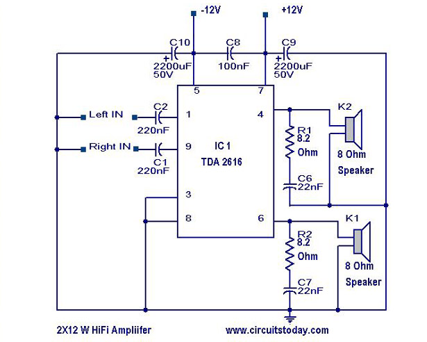
A simple Hi-Fi amplifier circuit diagram with a schematic for creating an audio amplifier, designed using the TDA 2616 integrated circuit (IC), which is a stereo power amplifier. It is suitable for use with radios, tape players, and televisions,...
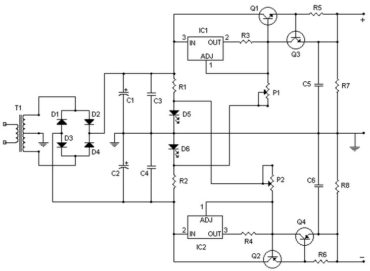
This circuit can deliver up to 15V per section (-15V and +15V), or up to 30V as a whole, for a maximum consumption of 2A. With modifications, it could be adjusted to provide up to 5A or more. Transistors...
The oscillator was designed to utilize resistors and capacitors instead of large low-frequency LC tank circuits for generating audio frequencies. It achieved low distortion (less than 0.5%) by employing a two-stage amplifier with sufficient negative feedback to set the...