
48V Phantom (Microphone) Power Supply
 Power Supply")
Phantom power is a method used to provide power to condenser microphones through the same cables that carry the audio signal. This technique allows for a simplified setup, eliminating the need for separate power sources. Typically, the voltage is supplied at 48 volts, although some devices may operate at lower voltages such as 12 V or 24 V.
In a standard configuration, the phantom power is delivered through the two signal wires of a balanced audio cable, usually XLR connectors. The voltage is applied equally to both wires, with the microphone itself being designed to utilize this power for its internal preamplifier, which is essential for converting sound waves into an electrical signal.
The presence of phantom power does not affect dynamic microphones, which do not require external power to operate. However, when connecting a condenser microphone, it is crucial to ensure that the phantom power is enabled on the audio interface or mixer to avoid any signal issues.
Proper implementation of phantom power includes using high-quality cables and connectors to minimize noise and interference. Additionally, it is advisable to check the specifications of both the microphone and the audio equipment to ensure compatibility and prevent potential damage.
Overall, 48 V phantom power is a reliable and efficient method for powering professional condenser microphones, facilitating high-quality audio capture in various applications, including studio recordings, live performances, and broadcasting.48 V ‘phantom powering has become the standard for professional condenser microphones. The supply (or rather bias) voltage is applied over both wires of.. 🔗 External reference
Related Circuits
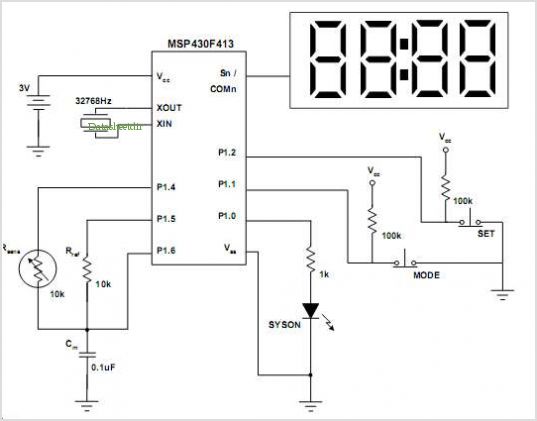
More: A comprehensive electronic schematic that outlines the design and functionality of a specific circuit is crucial for understanding its operation. The schematic should include components such as resistors, capacitors, diodes, transistors, and integrated circuits, along with their interconnections....
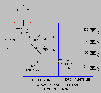
The circuit provides sufficient illumination suitable for reading purposes. Capacitor CX, in conjunction with diodes D1 through D4, constitutes the AC step-down circuit. CX lowers the high voltage AC from the mains to a low voltage AC, which is...
Vacuum tube electronic circuits operate from relatively high DC voltages (150 to 600 volts). The Electric Utility supplies 120 volts AC. Transformers can step up the 120 volts AC line voltage to the necessary range, but it remains AC....
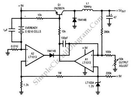
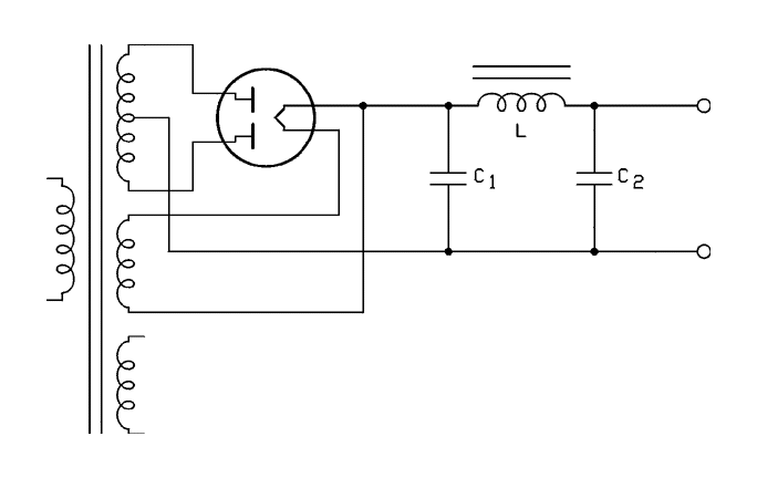
A circuit of a low-power switching regulator is illustrated in the schematic diagram below. This circuit can provide an output voltage of 5V from a 9V source. The efficiency... The low-power switching regulator circuit is designed to convert a higher...
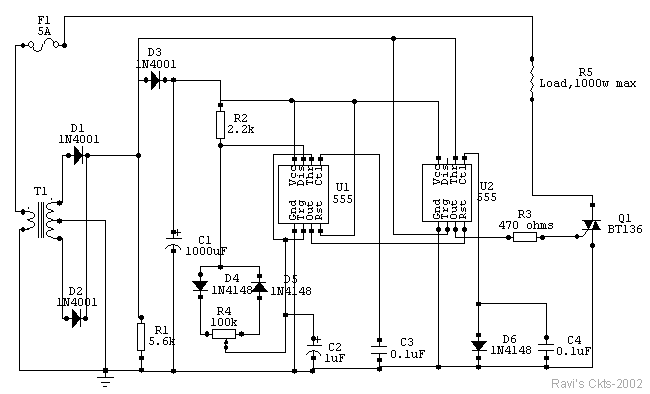
The circuit is constructed using two 555 timer integrated circuits, designated as U1 and U2. U1 is configured as a variable duty cycle oscillator with a fixed time period of approximately 0.1 seconds. The duty cycle can be adjusted...
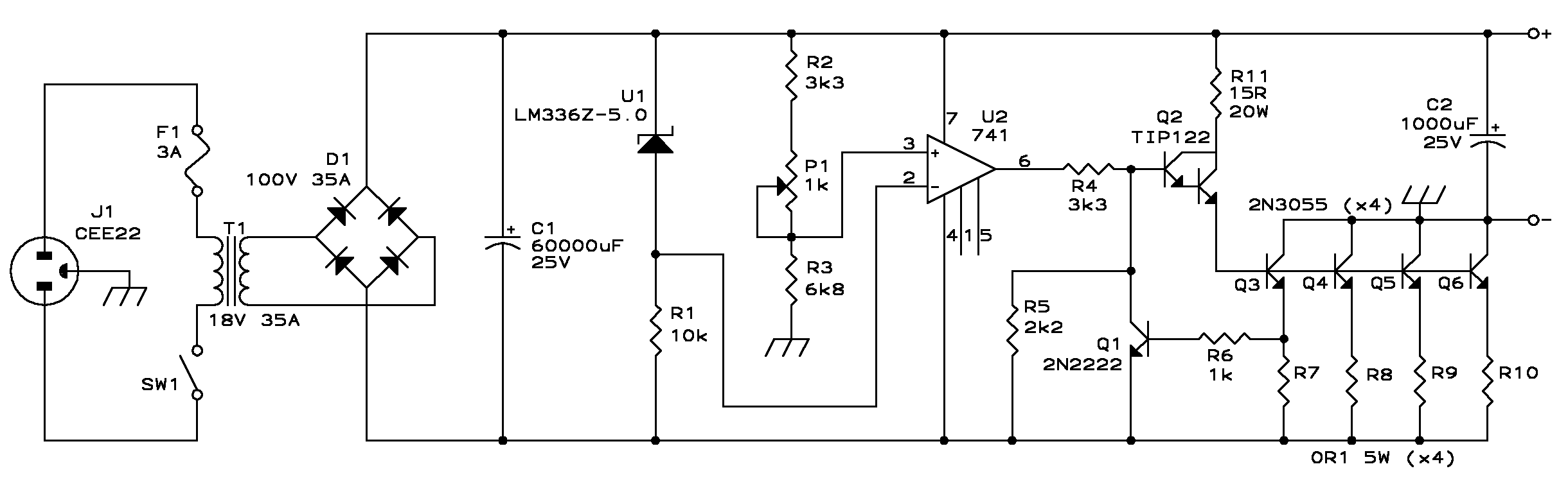
The presented design features an unconventional arrangement that provides certain advantages compared to traditional designs. To begin with, a linear power supply incorporates a transformer that steps down the line voltage to a level higher than the regulated output...