
ANTENNA DESIGN FOR FM TRANSMITTER
This configuration describes a basic antenna system utilizing two aluminum rods as the radiating elements. The rods serve as a dipole antenna, where each rod acts as one half of the dipole. The insulator between the rods is crucial as it prevents electrical contact, ensuring that the two rods operate as separate conductive elements.
The choice of a 75-ohm cable is standard for television antennas, as this impedance matches the typical input impedance of many TV tuners, optimizing power transfer and minimizing signal reflections. The central feed point is where the coaxial cable connects to the antenna, typically at the junction of the two rods. This connection point is critical for the performance of the antenna, as it influences the radiation pattern and impedance characteristics.
To ensure effective operation, the length "L" of each aluminum rod should be approximately half the wavelength of the target frequency for which the antenna is designed. The formula to calculate the resonant frequency (f) based on the length of the dipole antenna is given by:
\[ f = \frac{c}{2L} \]
where \( c \) is the speed of light, approximately \( 3 \times 10^8 \) meters per second. This relationship indicates that the antenna will be most effective at resonating at frequencies where the length of the rods corresponds to the wavelength of the radio waves.
In practical applications, the installation height, surrounding environment, and orientation of the antenna will also significantly affect its performance. Proper grounding and weatherproofing of the aluminum rods and connections can enhance durability and signal quality, making this antenna design suitable for various applications, including receiving broadcast television signals.Two aluminum rods, each of length "L" in meters are joined together through an insulator as shown in fig. From center, 75 ohm cable is feeded just like ordinary TV antenna. 🔗 External reference
Related Circuits
The circuit consists of a few components, specifically four, to create a miniature wireless FM microphone. It operates with a stable frequency, achieving a range of over 10 meters with a 1.5V supply and a current consumption of less...
This two-stage design utilizes enhancement-mode pHEMT device technology to support IEEE 802.11a, HiperLAN2, and HiSWANa local-area network receivers. The two-stage design is characterized by its use of enhancement-mode pHEMT (pseudomorphic High Electron Mobility Transistor) technology, which is essential for achieving...
P1 acts as the volume level for the condenser microphone. For the FM transmitter, the coil will be small. It is recommended to use thin gauge enamel magnet wire. The diameter of the coil should be a couple of...
This circuit explains alternate wireless switching using an ultrasonic sensor. The distance of the switching range should be more than 10 meters. The described circuit employs an ultrasonic sensor to facilitate wireless switching, allowing for the activation or deactivation of...
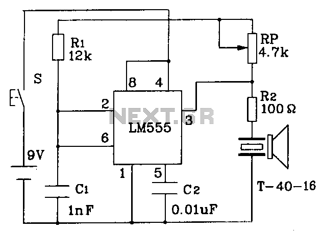
The circuit operates at a distance of 3 feet from the oscillating pulse output of a 555 timer generating a 40kHz signal, driving a T-40-16 transducer to emit ultrasonic signals at the same frequency. The circuit is powered by...
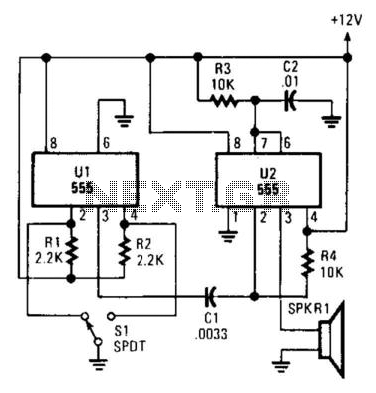
Pulsed sound is produced by this circuit. U1 is used as a bistable multivibrator, which acts as a contact debouncer for S1. C1 feeds a trigger pulse to U2, which then generates a pulse to SPKR1, a piezo transducer....