
Acoustic Sound Transmitter
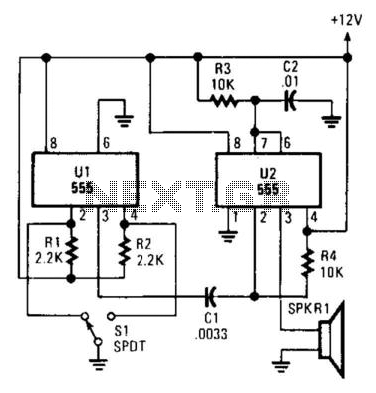
The circuit described produces pulsed sound through the operation of a bistable multivibrator and a piezo transducer. The primary component, U1, functions as a bistable multivibrator, which is essential for ensuring stable transitions between two states. This characteristic is particularly useful in debouncing a mechanical switch, denoted as S1. When the switch is activated, it may produce multiple unwanted transitions due to mechanical bounce. The bistable multivibrator effectively filters these bounces, providing a clean output signal.
The capacitor C1 plays a crucial role in the timing aspect of the circuit. It is connected to the output of U1 and is responsible for generating a trigger pulse that is sent to U2. U2 is likely configured as a monostable multivibrator or a similar pulse-generating circuit, which receives the trigger from C1 and produces a defined output pulse. This output pulse is then directed to SPKR1, which is identified as a piezo transducer. The piezo transducer converts the electrical pulse into audible sound.
The design specifies a pulse width of 110 µs, which indicates the duration of the output signal generated by U2. This pulse width is critical as it determines the characteristics of the sound produced by the piezo transducer. A pulse width of 110 µs typically results in a short, sharp sound, suitable for applications such as alarms, indicators, or notifications.
In summary, this circuit effectively combines a bistable multivibrator for debouncing a switch, a timing capacitor for pulse generation, and a piezo transducer for sound output, resulting in a reliable and efficient pulsed sound generation system. Pulsed sound is produced by this circuit. Ul is used as a bistable multivibrator, which acts as a contact "debou ncer" for SI. CI feeds a trigger pulse to U2, which feeds a pulse to SPKR1, to piezo transducer. Values are shown for a pulse width of 110uS. 🔗 External reference
Related Circuits
This circuit is a simple two-transistor (2N2222) mini FM transmitter. No authorization is required for this transmitter according to FCC regulations regarding wireless microphones. When powered by a 9-volt battery and equipped with an antenna no longer than 12...
This circuit utilizes a 74HC14 hex Schmitt trigger inverter as a square wave oscillator to drive a small signal transistor configured in a class C amplifier. The oscillator frequency can be set to a fixed value using a crystal...
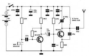
Simple FM Transmitter Circuit This simple FM transmitter circuit was built using a transistor with a transmission distance of about 300m around your home. The simple FM transmitter circuit utilizes a transistor to modulate audio signals onto a radio frequency...
This rain sound effects generator circuit simulates the sound of rain and can be utilized in electronic music and radio shows. The noise source employs a germanium diode that is directly polarized and subsequently amplified by a single-stage amplifier...
This transmitter needs heatsink at 2N2219. With the C4 we regulate the frequency. With their C7, C8 we adapt the resistance of aerial (practically to them we regulate so that it is heard our voice in the radio as...
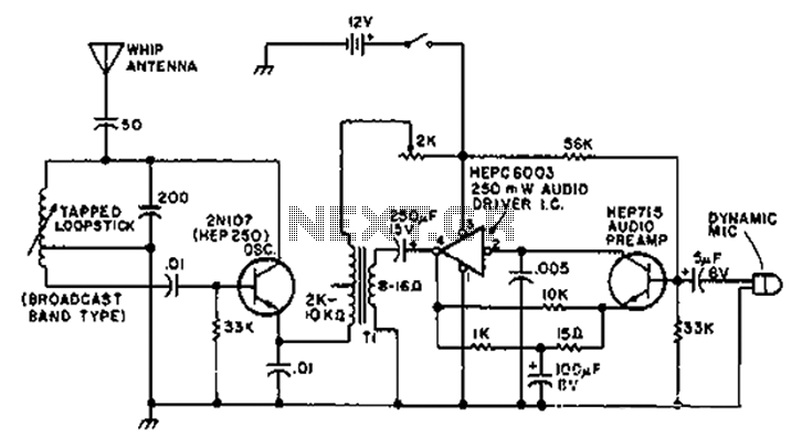
A circuit diagram of the T1 is a low-impedance output transformer, featuring a 5000-8 ohm resistor. The T1 low-impedance output transformer is designed to match the output of audio amplifiers to the impedance of loudspeakers, ensuring optimal power transfer and...