
Ultrasonic Transmitter Sensor Switch circuit
The described circuit employs an ultrasonic sensor to facilitate wireless switching, allowing for the activation or deactivation of devices based on distance measurements. The ultrasonic sensor operates by emitting high-frequency sound waves and measuring the time taken for the echo to return after bouncing off an object. This time is then converted into a distance measurement, which is compared against a predetermined threshold to determine whether the switching action should occur.
For implementation, the circuit requires a microcontroller unit (MCU) to process the signals from the ultrasonic sensor. The MCU is programmed to continuously monitor the distance readings. When an object is detected within the specified range (greater than 10 meters in this case), the microcontroller triggers a wireless transmitter module, such as a radio frequency (RF) transmitter or a Wi-Fi module, to send a signal to a corresponding receiver module connected to the target device.
Power supply considerations are critical, as the circuit must operate effectively over the intended distance. A stable power source, such as batteries or a regulated power supply, should be used to ensure consistent operation of the ultrasonic sensor and the microcontroller. Additionally, the design may include features such as low-power modes to extend battery life during periods of inactivity.
A feedback mechanism could also be incorporated, allowing the system to confirm the successful execution of the switching action. This could involve the use of LEDs or other indicators to provide visual confirmation when a command has been successfully transmitted and received.
Overall, the circuit represents a versatile solution for wireless switching applications, leveraging ultrasonic sensing technology to achieve operational ranges exceeding 10 meters.This circuit explain about alternate wireless switching using ultrasonic sensor. The distance of switching range should be more than 10 meters .. 🔗 External reference
Related Circuits

In this circuit, data at input C is amplified by IC2 and then fed to modulator IC1. IC1 generates two frequencies, depending on the values of C5, I10, R5, Rn, and R6. The frequency f1 is generated if pin...
The circuit consists of a PIC microcontroller, an in-circuit serial programming (ICSP) interface, an RS232 level translator, and an HD44780 LCD display. Initially, a scrolling message is shown using the show_intro function. When a serial input is detected, the...

This 1000-watt power inverter circuit diagram is based on the MOSFET RF50N06. For increased power output, additional MOSFETs can be paralleled with the RF50N06. These MOSFETs are rated for 60 volts and 50 amps. It is essential to connect...
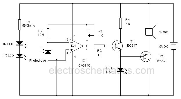
This infrared alarm barrier is designed to detect individuals passing through doorways, corridors, and small gates. The transmitter emits an infrared light beam that is not visible to the human eye. When the beam is interrupted by a person,...
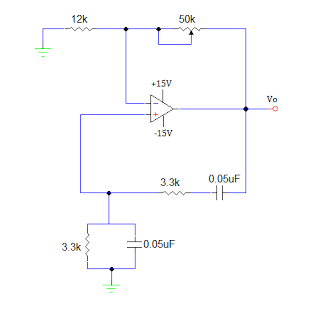
An operational amplifier-based sine wave generator circuit, commonly known as a Wien bridge oscillator, is recognized for its simplicity and stability. The Wien bridge oscillator connects the Wien bridge circuit between the amplifier's input and output terminals. The bridge...
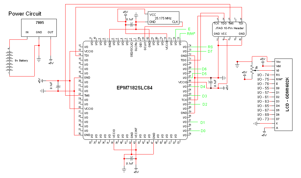
The schematic for this project is a modified version of the CPLD development board schematic. Several new components have been added for this project, and the completed schematic is presented below. The primary components in the schematic include the...