
anti theft security for car audios
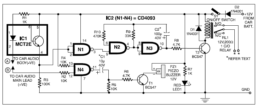
The circuit described operates on a 12V DC supply sourced from a car battery, utilizing various components to create a security system for the car audio unit. The initial state of the system is indicated by LED1, which confirms that the circuit is in standby mode when switch S1 is closed. The optocoupler IC1 plays a critical role in isolating the control signals from the car audio system, ensuring that the primary circuit remains inactive until a disruption is detected.
In the event of an unauthorized removal of the car audio, the circuit's response is triggered by the loss of the ground connection at the optocoupler's cathode. This disconnection allows the oscillator circuit, constructed around gates N2 and N3, to activate. The oscillator generates a square wave signal that drives transistor T2, which in turn controls relay RL1. The relay's contacts can be configured to activate various alarm systems, such as beepers or indicators, depending on user preference.
Capacitor C2 is integral to determining the timing characteristics of the relay operation. By selecting different capacitance values, the user can customize the duration for which the relay remains energized, thus tailoring the alarm response to their specific needs. For instance, a 100 µF capacitor results in a balanced 5 seconds of activation followed by 5 seconds of deactivation.
The circuit also incorporates a differentiating circuit formed by capacitor C1 and resistor R5, which generates a short pulse when the ignition key is turned off. This pulse momentarily turns on transistor T1, allowing the buzzer to sound briefly, providing an audible indication of the ignition status. The timing of this buzzer activation can be adjusted by varying the values of C1 and R5, enabling further customization of the alert features.
In summary, the described circuit effectively combines a security mechanism with customizable timing features to protect the car audio system against unauthorized removal. Proper installation of the LED and buzzer on the dashboard, along with strategic placement of switch S1, enhances the usability and effectiveness of the system.When 12V DC from the car battery is applied to the gadget (as indicated byLED1) through switch S1, the circuit goesinto standby mode. LED insideoptocoupler IC1 is lit as its cathode terminalis grounded via the car audio (amplifier)body.
As a result, the output atpin 3 of gate N1 goes low and disablesthe rest of the circuit. Whenever an attempt is made to removethe car audio from its mounting bycutting its connecting wires, theoptocoupler immediately turns off, as itsLED cathode terminal is hanging. As aresult, the oscillator circuit built aroundgates N2 and N3 is enabled and it controlsthe on`/off` timings of the relay viatransistor T2.
(Relay contacts can be usedto energise an emergency beeper, indicator, car horns, etc, as desired. ) Different values of capacitor C2 givedifferent on`/off` timings for relay RL1 tobe on`/off`. With 100 F we get approximately5 seconds as on` and 5 seconds asoff` time. However, when one switches off the ignitionkey, the supply to the car audio isalso disconnected. Thus the output of gateN4 jumps to a high` state and it providesa differentiated short pulse to forward biastransistor T1 for a short duration. (Thecombination of capacitor C1 and resistorR5 acts as the differentiating circuit. ) This on` periodof buzzer can bevaried by changingthe values ofcapacitor C1and/or resistorR5. After construction, fix theLED and buzzerin dashboard asper your requirementandhide switch S1in a suitable location.
🔗 External reference
Related Circuits
The circuit diagram focuses on the research and design features applied to mobile robots. The design considers small size, low power consumption, and ease of movement, catering to home users with a user-friendly display interface. For speech recognition, a...
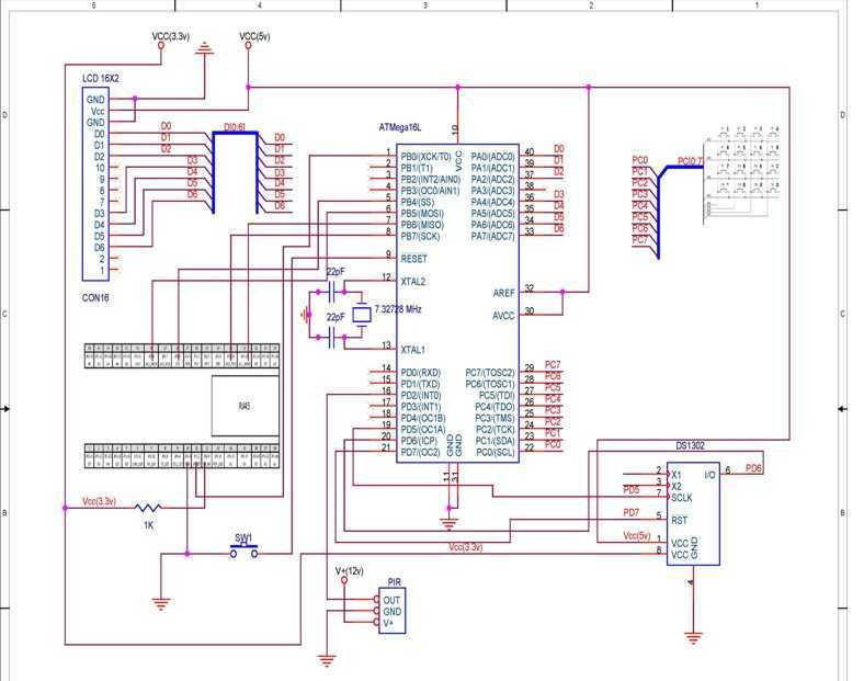
TCP based security system using the Ethernet module offered within the contest, an ATmega16L microcontroller, a PIR as a sensor and few other peripheral devices, which is specially targeted for homes and small business owners. I have used through...
This circuit employs the widely used and easily accessible LM3914 integrated circuit (IC). The LM3914 is straightforward to operate, does not require external voltage regulators due to its built-in voltage regulation, and can be powered by a variety of...
This is a computer I built for my car, its an MP3 music system but can also do other tasks. Based around a super-small sub-micro ATX motherboard from a computer known as the BookPC BKi810, I have put the...
Whenever I'm in the car listening to my favourite CD, it always happens - my batteries go dead. To solve that problem, I built this extremely simple regulator circuit. It steps down the 12V from the lighter socket to...
When the amplifier is installed inside the suitcase, it will require a change to stop working. The LA47536 has a control pin (pin 4) that requires a small voltage of up to 2V to turn on the amplifier. Transistors...