
Portable CD Player Adapter For Car

The described circuit functions as a voltage regulator designed to convert the 12V supply from a car's lighter socket to a lower voltage suitable for powering a CD player, specifically stepping down to 9V. The circuit utilizes a linear voltage regulator from the 78xx series, which is well-known for its reliability and ease of use in various applications.
The basic configuration includes the following components:
1. **Input Capacitor (C1)**: Typically, a 0.33 µF ceramic capacitor is placed at the input of the regulator to filter out any high-frequency noise from the power supply. This ensures a stable input voltage to the regulator.
2. **Voltage Regulator (IC1)**: The heart of the circuit is the 78xx series voltage regulator, which steps down the voltage. For a 9V output, the specific model would be the 7809. The pin configuration generally includes an input pin, ground pin, and output pin, which makes it easy to implement in various designs. The 78xx series regulators are designed to provide a stable output voltage with a maximum current rating that varies by model (up to 1A for the 7809).
3. **Output Capacitor (C2)**: A 0.1 µF ceramic capacitor is connected to the output pin to improve transient response and stability of the output voltage. This capacitor helps to maintain a steady voltage during sudden load changes.
4. **Heat Sink (optional)**: Depending on the current drawn by the CD player, a heat sink may be necessary for the voltage regulator to dissipate heat efficiently. This is particularly important if the CD player operates near the maximum current rating of the regulator, as excessive heat can lead to thermal shutdown or damage.
5. **Wiring**: Proper wiring is essential to ensure reliable operation. The input should be connected to the car's lighter socket, while the output should be routed to the CD player's power input. It is advisable to use appropriately rated wires to handle the current without significant voltage drop.
This circuit is versatile, as the same layout can be adapted for various output voltages by substituting the appropriate regulator from the 78xx series, which has a standardized pin configuration. This universality allows for easy customization based on the specific requirements of different CD players or similar devices.Whenever I`m in the car listening to my favourite CD, it always happens-my batteries go dead. To solve that problem, I built this extremely simple regulator circuit. It steps down the 12V from the lighter socket to 9V which is used by the CD player. Different CD players (I have a Sony Discman) may require different voltages, so just use the correct regulator. All the 78xx series regulators have the same pin out, so the circuit is universal. 🔗 External reference
Related Circuits
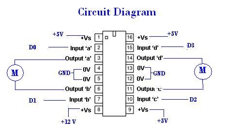
A remote Sun SPOT will transmit data to a Sun SPOT mounted on a car, which will control an integrated circuit (IC) according to the digital input/output pins D0 to D3. The IC will subsequently drive the motors that...
There are monitors that feature only three BNC inputs and utilize composite synchronization (sync on green). This circuit has been specifically designed for such monitors. The design maintains simplicity while delivering reasonable performance. The operational principle is straightforward. The...
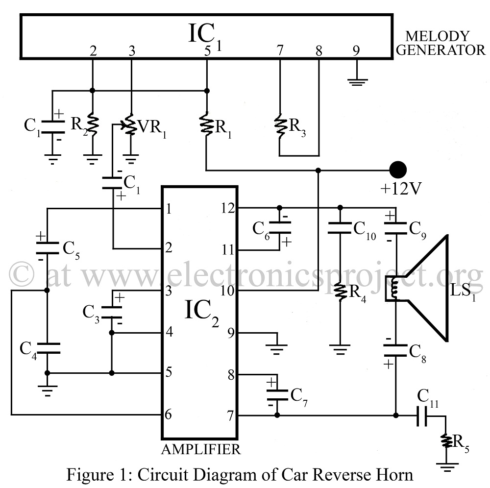
The Car Reverse Horn is a circuit designed for use in vehicles, utilizing a melody generator integrated circuit (IC) CTC2877 in conjunction with an amplifier IC AN7148. This circuit diagram facilitates the implementation of a reverse horn system in...
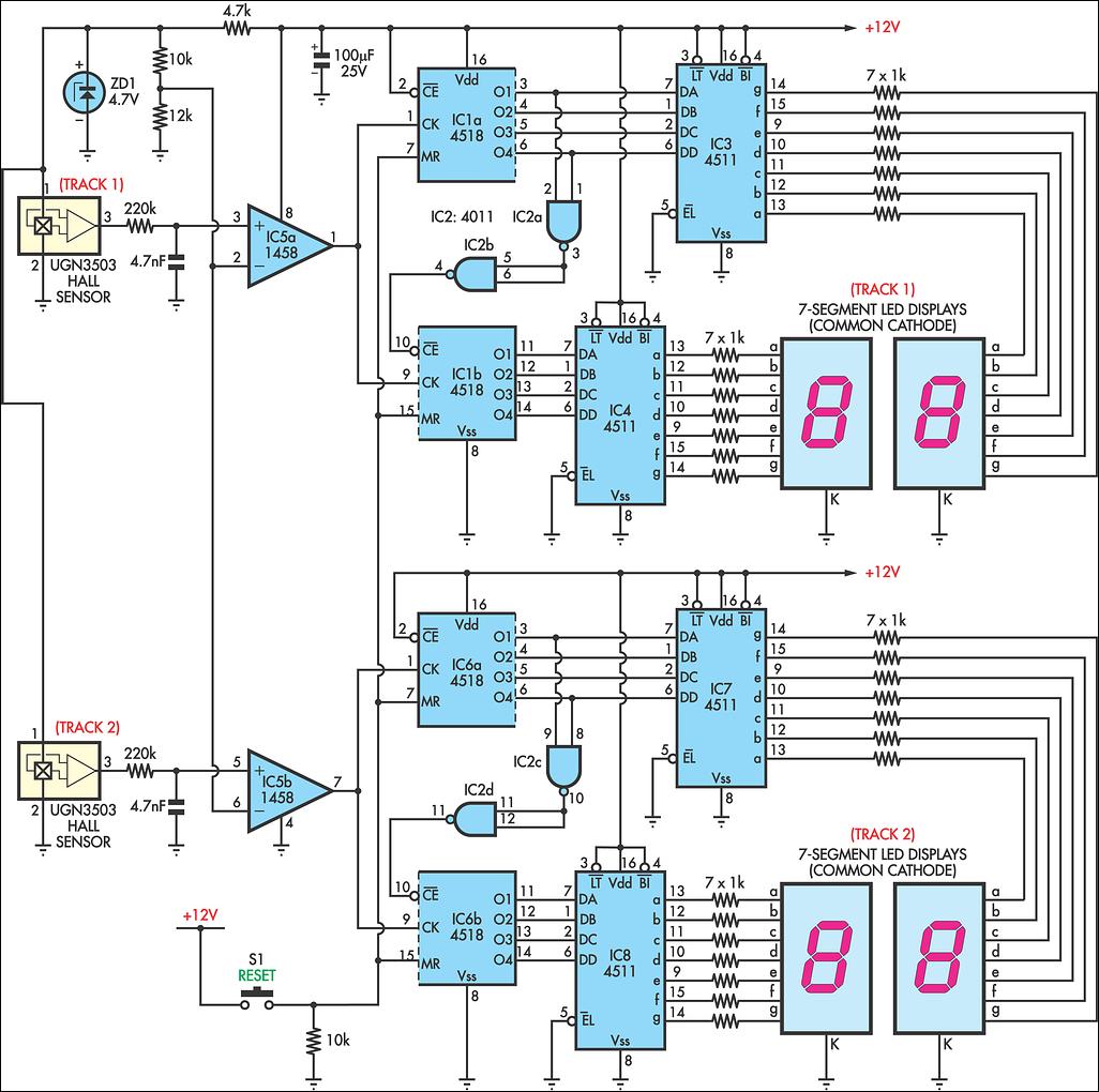
AFX slot car sets are enjoyable, and the experience can be enhanced with a lap counter. This circuit counts from 00 to 99, featuring independent counters for each track. The sensing device utilized is a Hall effect sensor (UGN3503),...
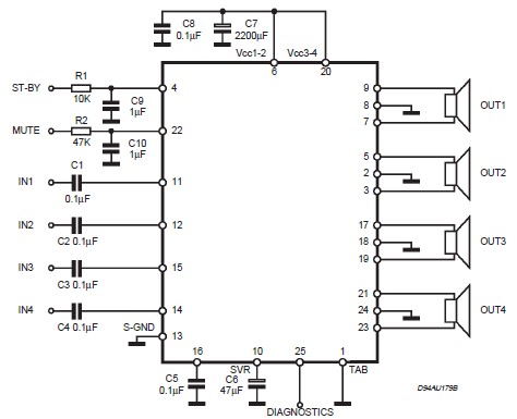
This circuit illustrates a car audio amplifier utilizing the TDA7381 integrated circuit (IC). The TDA7381 audio amplifier IC allows for the design of a straightforward 4x25 watts car radio. The TDA7381 is a high-performance audio amplifier designed specifically for automotive...
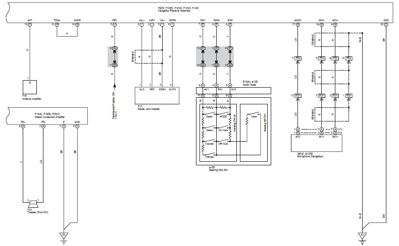
This document contains the wiring diagram for the 2007 Toyota Camry, specifically for the GSV40 and ACV40 series. It details the electrical circuits present in the vehicles, categorizing them by system for clarity. The wiring for each system is...