
Simple but reliable car battery tester
The LM3914 is a bar graph or LED dot display driver that can control up to ten LEDs in a linear or dot mode. It is designed to provide a visual representation of an analog voltage level. The circuit typically consists of the LM3914 IC, a series of LEDs, and a voltage divider or potentiometer to set the reference voltage for the input signal.
To construct the circuit, the input voltage is applied to the appropriate pin of the LM3914, which internally compares this voltage against a reference voltage determined by the external resistors. The IC's output pins are connected to the anodes of the LEDs, while the cathodes are connected to ground through current-limiting resistors.
The operation is straightforward: as the input voltage increases, the corresponding number of LEDs light up in sequence, providing a clear visual indication of the voltage level. This feature makes the LM3914 ideal for applications such as battery level indicators, audio level meters, and other visual display systems.
In addition, the LM3914 can operate with a supply voltage range from 3V to 25V, making it versatile for various electronic projects. It is essential to ensure that the current through each LED does not exceed the maximum rating, typically achieved by selecting appropriate resistor values.
Overall, the LM3914 circuit is an effective and visually appealing solution for monitoring analog signals, and its simple design allows for easy integration into a wide range of electronic applications.This circuit uses the popular and easy to find LM3914 IC. This IC is very simple to drive, needs no voltage regulators (it has a built in voltage regulator) and can be powered from almost every source. Electronics project.. 🔗 External reference
Related Circuits
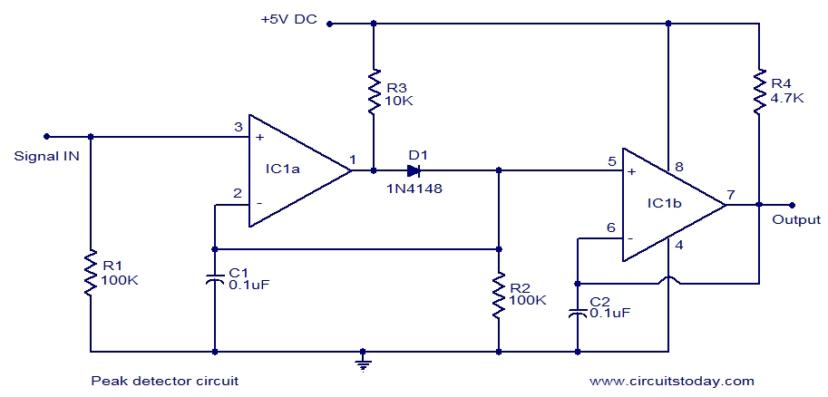
LM339-based peak detector circuit. Simple and easy to construct. Operates from a 5V DC single supply. LM339 is a dual comparator. The LM339-based peak detector circuit is designed to capture and hold the peak value of an input signal. This...
The hex switches are connected to J2 as follows: pin 1 is the common of both switches (+5V), pin 2 is the least significant bit (LSB) up to pin 5 which is the most significant bit (MSB) of the...
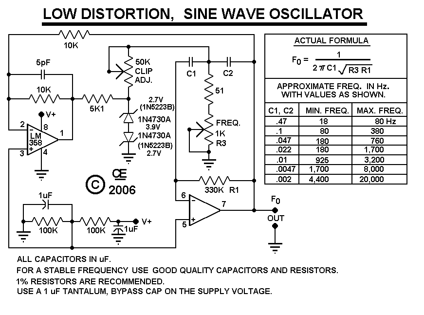
After constructing the device, adjust the frequency to the desired level using the "Frequency Control." Then, utilize an oscilloscope to fine-tune the waveform for optimal performance with the "Clip Control." The sharp rise and fall times of square waves...

The circuit utilizes a dual operational amplifier integrated circuit (IC), specifically the 1458, which contains two separate op-amps within a single package. In this configuration, the first op-amp functions as a voltage follower, directing its output to charge capacitor...
This design will appeal to technicians working with pneumatically operated valves and other devices controlled by a 4-20mA current loop. While 4-20mA signal injectors and calibrators are available, this particular model is cost-effective to construct and user-friendly. Upon initial...
This circuit utilizes the LT1074CT switching regulator integrated circuit (IC). For a more comprehensive explanation of the design, it is recommended to refer to Application Note AN35 published by Linear Technology. The schematic illustrates the LT1074CT functioning as a...