
Aquarium Auto Controller using PIC18F4520
- Time / calendar
- Weekly timer for 6 daily events
- Digital temperature sensor
- Additional EEPROM memory
- 8 outputs controlled by relays joinable to timer events (2 of them can be joined to temperature sensor)
- LCD display 4x20
- 8 bicolor LEDs associated with output ports
- RS232 serial port for PC communication.
The AquaCont firmware was conceived from the idea of A. Di Stefano's "macchina a stati," published in his article "Realizzazione di un timer digitale programmabile" on the 257n of the "Fare Elettronica" Italian magazine; the original code was obviously modified for making it compatible with the new hardware and new needs. In the new code, new I2C functions for communication with the Dallas RTC DS1307, the temperature sensor Maxim DS18S20, and the EEPROM memory 24LC16 have been implemented, and using the USART functions library, for the RS232 serial port. The original idea of a states structure remained unchanged, even if it was implemented with new functionalities and at the same time, updating those already existing. The states diagram structure is shown in Fig.4. The stato variable determines which of the seven functions will be executed in the main loop. Every single function is independent and permits modifying the state in relation to the pressed button.
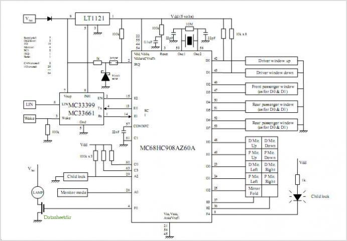
The AquaCont system integrates various electronic components and subsystems to achieve its functionality. The central processing unit, the PIC18F4520, serves as the main controller, coordinating the operations of the temperature sensor, real-time clock, and relay outputs. The real-time clock, powered by a lithium battery, ensures accurate timekeeping even during power outages, while the temperature sensor provides critical data for maintaining optimal aquarium conditions.
The relay outputs are managed through optocouplers, which provide necessary electrical isolation between the microcontroller and high-voltage systems, thus enhancing system safety. The system's dual power supply architecture—5V for the microcontroller and 12V for the relay board—ensures that the microcontroller is protected from potential overvoltage conditions.
Programming the AquaCont is facilitated through an RS232 serial connection to a PC, where users can utilize the WinTimer software for configuration. This software allows users to set weekly timer events, adjust temperature sensor parameters, and assign descriptive labels to each relay output, enhancing user interaction. The use of additional EEPROM memory (LC2416) allows for storing configuration settings and relay descriptions, ensuring that user preferences are retained even after power loss.
The LCD display (4x20) provides a user-friendly interface for monitoring the system's status, including real-time temperature readings, current time, and the operational status of each relay. The inclusion of bicolor LEDs associated with each relay output offers visual feedback on the state of the system, aiding in quick diagnostics and operational awareness.
The firmware developed in mikroC utilizes an extensive library of functions, facilitating efficient programming and system management. The modular design of the firmware, which allows for independent state functions, enhances the system's flexibility and responsiveness to user inputs, further contributing to the AquaCont's effectiveness as an aquarium management solution.The AquaCont is an electronic system witch permits to manage and to monitor most of the parameters of all the electrics devices that can be found in a aquarium. The PIC18F4520 used to realize it, combines a real time clock and a temperature sensor in order to control 8 relays.
The LCD display permits to monitor the current date and time, the temperature detected by the sensor and moreover it permits to visualize each port status in the last row. In the following LCD screens display it is possible to program the weekly timer events, set the temperature sensor parameters and manage the serial connection with a PC where is running the included WinTimer software.
The power supply needed by the main board is 5V, while the relays board requires 12V; the different source power was useful in granting the protection of the microcontroller and his circuits from overvoltage and short circuit on the 220V. Two optocouplers are utilized for that purpose ensuring the isolation of the different voltages. The weekly timers are programmed basing on the clock provided by the proper integrated circuit supplied with a lithium battery.
The timers data are memorized in the micro's eeprom. The RS232 serial port allows to simply program the micro using the corresponding PC software; the functions provided in the PC software are also included in the firmware, except for the PC clock syncing. Using the Pc software is also possible to assign a description, to each of the 8 relays ports that will be memorized in the additional LC2416 eeprom memory.
In this memory will be also stored the temperature sensor's settings data. The mikroC language is known for its large functions library and for its good development board so it was used for developing the AquaCont firmware. In fact the first AquaCont prototype was developed using the MikroElektronika's EasyPIC4 and two breadboards.
Please note that the firmware's source code can be recompiled only using a registered version of MikroC compiler, while the freeware version limits its output to 2K program words. The system main characteristics are: time / calendar weekly timer for 6 daily events digital temperature sensor additional eeprom memory 8 outputs controlled by relays joinables to timer events ( 2 of them that can be joined to temperature sensor) LCD display 4x20 8 bicolour LEDs associated to output ports RS232 serial port for PC communication.
The AquaCont firmware was conceived from the idea of A. Di Stefano's ?macchina a stati?, published in his article ?Realizzazione di un timer digitale programmabile? on the 257n of the ?Fare Elettronica? Italian magazine; the original code was obviously modified for making it compatible with the new hardware and new needs.
In the new code have been implemented some new I2C functions for the communication with the Dallas RTC DS1307, the temperature sensor Maxim DS18S20, the eeprom memory 24LC16 and, using the USART functions library, for the RS232 serial port. The original idea of a states structure remained unchanged even if it was implemented with new functionalities and at the same time, updating those already existing.
In Fig.4 it is shown the states diagram structure. The stato variable determines which one of the seven function will be executed in the main loop. Every single function is independent and permits to modify the state in relation to the pressed button. 🔗 External reference
Related Circuits
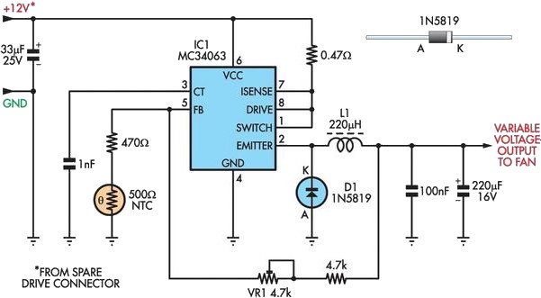
A partial solution to reducing noise from PCs can be achieved by lowering the speed of internal cooling fans. Low-cost fan speed controllers are available, but they often utilize inefficient, heat-generating linear regulators and lack a temperature feedback mechanism....
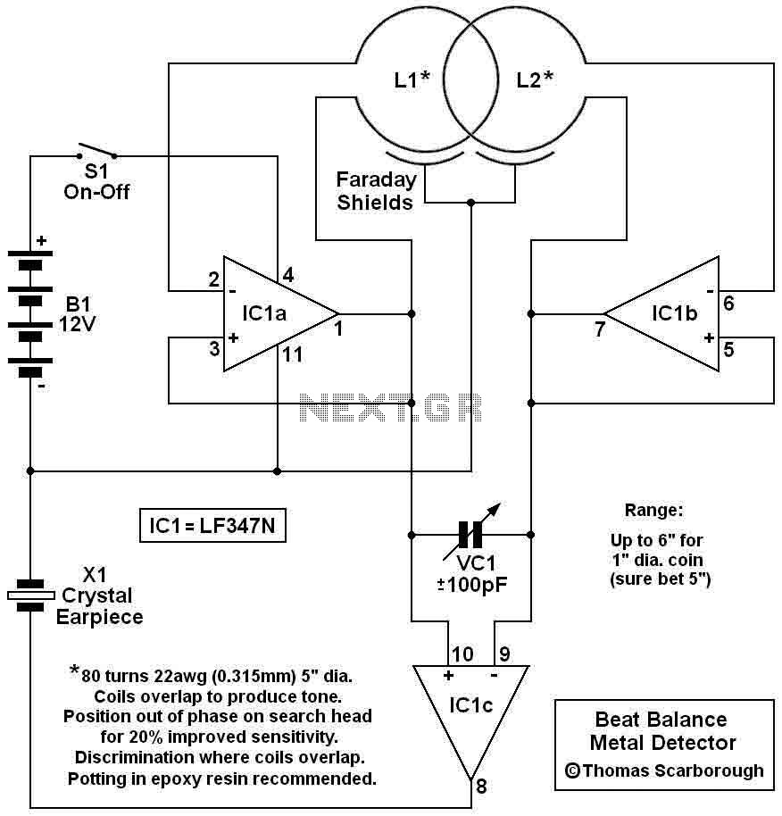
Here's a metal detector circuit that frequencies of the two oscillators are then mixed in similar fashion to BFO, to produce an audible heterodyne. On the surface of it, this design would seem to represent little more than a...
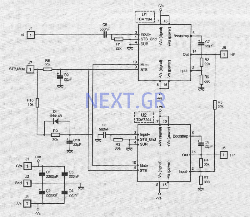
The TDA 7294 from T-MICROELECTRONICS is a monolithic integrated circuit housed in a "Multiwatt 15" package, primarily designed for use in Class AB amplifiers for high-fidelity applications, including stereo systems, active speakers, and television receivers. Its large feed area...
The CDCF5801 provides clock multiplication from a reference clock (REFCLK) signal with the unique capability to delay or advance the CLKOUT/CLKOUTB with steps of only 1.3 mUI through a phase aligner. For every rising edge on the DLYCTRL pin,...
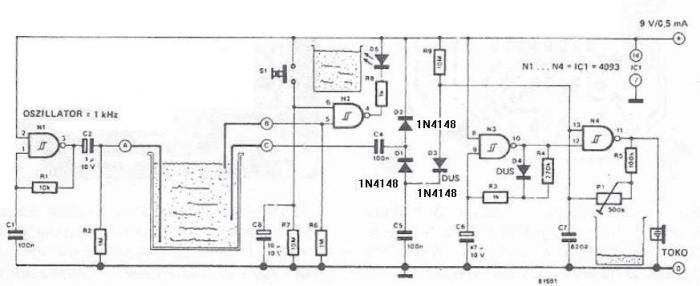
The circuit diagram is straightforward and operates as follows: the N1 Schmitt trigger functions as an oscillator, producing a frequency of approximately 1 kHz. When there is sufficient water in the tank, alternating voltage flows from electrode A to...

The PR4403 is an improved version of the PR4402 40mA LED driver. It features an additional input known as LS, which can be set to a low state to activate the LED. The PR4403 LED driver is designed to...