
Hydro alarm circuit diagram using CMOS

The circuit utilizes a Schmitt trigger (N1) to create a stable oscillation at around 1 kHz, which is essential for the operation of the water level monitoring system. The N1 Schmitt trigger ensures that the output is not affected by noise, providing a reliable oscillation that drives the subsequent components. The alternating voltage generated by the oscillator is directed from electrode A to electrode C, where it is rectified by diodes D1 and D2. This rectification is crucial as it converts the AC signal into a DC signal that can be interpreted by the logic gate at pin 13 of N4.
When the water level is adequate, the output at pin 13 remains low, preventing the buzzer from sounding. However, once the water level falls below the threshold, electrode C loses contact with water, causing N4 to become unblocked. This transition activates the buzzer, which emits sound at regular intervals, alerting users to the low water level. The timing of the alarm is controlled by the combination of oscillator capacitor N3 and capacitor C6, which dictate how long the buzzer remains active.
Moreover, the circuit includes a manual override feature via the S1 button. When pressed, this button temporarily activates LED D5, providing a visual indication that the water has reached electrode B. This LED is designed to turn off after approximately 10 seconds, which helps manage power consumption effectively.
The circuit is designed to operate within a supply voltage range of 5 to 15 V. It is important to consider that if the voltage is set below 9 V, the surface area of electrode C must be larger than that of electrode B to ensure proper operation. This requirement arises from the inherent signal loss that occurs through diodes D1 and D3, which can affect the performance of the monitoring system.
In summary, this water level monitoring circuit is an efficient and effective solution for detecting low water levels in a tank, utilizing a combination of oscillators, rectifiers, and logic gates to provide both audible and visual alerts. The design ensures reliability and power efficiency, making it suitable for various applications.Circuit diagram is very simple and works as follows: N1 Schmitt trigger works as an oscillator and produce a frequency of about 1 kHz. If in the tank is still enough water, then alternative voltage go from electrode A to electrode C. After rectified of diodes D1 and D2, at the pin 13 of the N4 reaches trough the D3 a logical "0". By this, the osci llator sound N4 and buzzer are disconnected. If the water level drops into such an extent that electrode C is no longer in contact with water, then blocking of N4 is suspended and buzzer starts to sound at regular intervals. Alarm duration is determined by the oscillator capacitor N3 and C6. The alarm stops as soon as the tank fills and electrode C is again in contact with water. If S1 button operates before filling D5 LED lights as soon as water reaches the electrode B. D5 turns off after about 10 seconds to load is not too much power. Supply voltage can be between 5 and 15 V. If you choose a voltage lower than 9 V, the electrode surface C must be much higher than that of electrode B.
This necessary because there is loss of signal from the electrode C in diodes D1. D3. 🔗 External reference
Related Circuits
The main purpose of this design is to address a minor flaw in the widely used Fridge Door Alarm circuit, which has been available on this website since 1999 and has been constructed by many hobbyists. This circuit ceases...

Many analog ohm meters have a non-linear scale, which results in poorer resolution at higher resistance values. This is due to the use of inexpensive current sources. Many analog ohm meters operate on a principle where the scale is not...
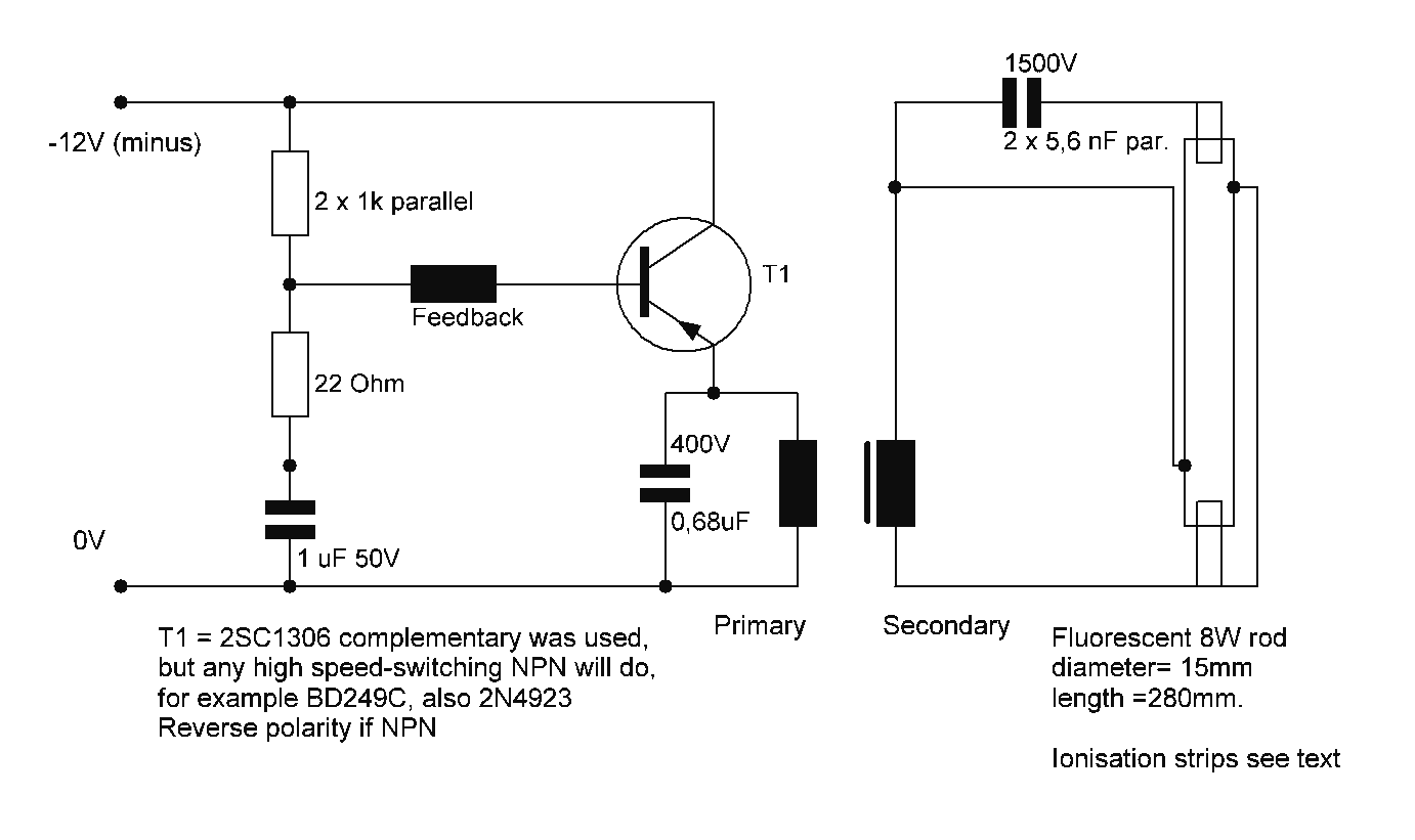
Starting a fluorescent lamp on an inverter can be challenging due to the trade-offs involved in achieving optimal operating efficiency with 12V drivers. Fluorescent lamps require a specific starting voltage to ionize the gas within the tube and initiate the...

Writing about multiple circuits in Marx, an entire new set has been discovered, referred to as "the" Marx Generator. There are diagrams available, along with a useful quote: "The main advantage of the Marx circuit configuration over a more...
This circuit utilizes a 555 timer to control a 4017 decade counter. The outputs from the counter are used to drive transistor relay drivers. The duration for which the lights remain "on" can be adjusted by modifying the connections...

Upon purchasing the slave dial, it arrived without instructions, packaging, or additional details. The only visible markings, aside from decades of grime, were on the face (SMITH SECTRIC, ACELEC SYDNEY) and some markings on the bracket holding the mechanism...