
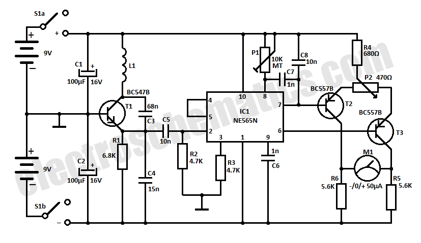
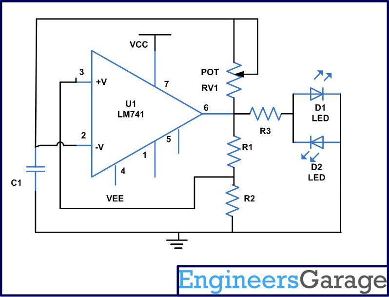
BFO Metal Detector using LF347N

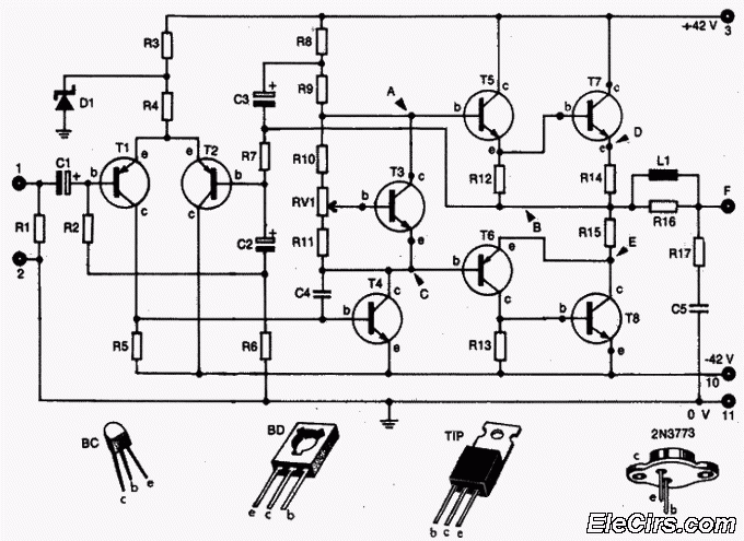
The described metal detector circuit employs a dual-oscillator configuration that operates on the principle of heterodyning, similar to a Beat Frequency Oscillator (BFO). This setup includes two oscillators whose frequencies are mixed to generate an audible signal that indicates the presence of metal. The fundamental operation relies on the interaction between these oscillators, which allows for the detection of metallic objects by producing a distinct audio tone when the frequencies are offset by the presence of conductive materials.
A key feature of this design is the mutual coupling between the two coils associated with each oscillator. This coupling alters the oscillation frequency of one oscillator in response to changes in the magnetic field generated by the other oscillator. As a result, when a metal object is introduced into the detection area, the frequency shift becomes more pronounced, enhancing the sensitivity of the circuit. This mutual interaction is a hallmark of Induction Balance (IB) metal detectors, which are known for their improved detection capabilities compared to traditional BFO designs.
The circuit can be further optimized by adjusting the inductance of the coils and the capacitance in the oscillator circuits, allowing for fine-tuning of the detection depth and sensitivity. Components such as variable capacitors may be incorporated to facilitate easy adjustments based on the operating environment. Additionally, the use of high-quality components in the oscillator design ensures stable operation, reducing the likelihood of false signals caused by environmental interference.
In summary, this metal detector circuit stands out due to its innovative use of mutual coupling between oscillators, resulting in enhanced sensitivity and detection range. The design exemplifies the principles of IB technology while maintaining the straightforward operational characteristics typical of BFO detectors.Here's a metal detector circuit that frequencies of the two oscillators are then mixed in similar fashion to BFO, to produce an audible heterodyne. On the surface of it, this design would seem to represent little more than a twinned BFO metal detector.
What makes the metal detector different above all else, and significantly increases its range, is that each coil modifies the frequency of the adjacent oscillator through mutual coupling. This introduces the "balance" that is present in an IB metal detector, and boosts sensitivity well beyond that of BFO.
🔗 External reference
Related Circuits
This homemade metal detector circuit will assist in locating objects made of materials with relatively high magnetic permeability. It is not suitable for detecting certain metals. This metal detector circuit operates on the principle of electromagnetic induction, utilizing a coil...
Many TOPSwitch TOP223 flyback power supply applications require two or more outputs to supply a variety of secondary circuits. Typical consumer applications of these multiple output converters include televisions and related products such as set-top decoders and video cassette...
Instructions for creating a Clap-Clap On/Clap-Clap Off switch circuit. This guide provides the necessary information for constructing a clap-activated switch. The Clap-Clap switch circuit is an innovative design that utilizes sound activation to control electronic devices. The primary components of...
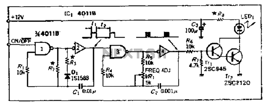
The 4000 Series 4011B is a NAND gate used in conjunction with a 4AI NAND gate circuit group to create two loops of an unstable multivibrator. The first NAND gate and the second NAND gate operate at approximately 1...
An astable multivibrator is an electronic device that continuously alternates between two states in its output. When one state is high, the other is low. This characteristic is useful for generating a continuous stream of pulses without the need...
Audio Amplifier with output power of either 100W or 130W. The output configuration can accommodate 2 transistors for 90W output or 4 transistors for 130W output. The PCB layout utilizes T3 on the heatsink. The component reference and values...