
arduino buzzer

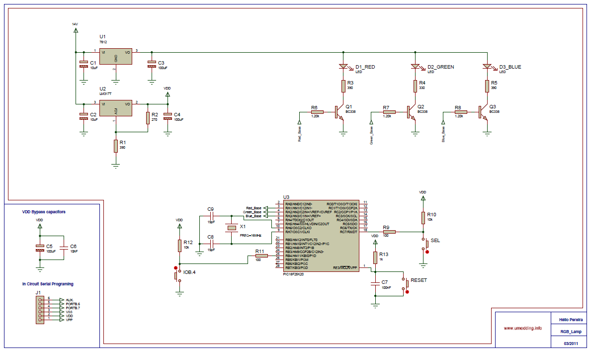
To implement this circuit, the following components are required: an Arduino board, a buzzer rated for a specific voltage (e.g., 5V or 12V), an NPN transistor (such as the 2N3904 or BC547), a resistor (typically 1kΩ for the base of the transistor), and a power supply suitable for the buzzer's operating voltage.
The connection process begins by identifying the pin configuration of the NPN transistor. The emitter of the transistor should be connected to the ground (GND) of both the Arduino and the buzzer's power supply. The collector of the transistor is connected to one terminal of the buzzer, while the other terminal of the buzzer connects to the positive terminal of the power supply.
Next, a resistor is connected to the base of the NPN transistor. The other end of this resistor is connected to one of the digital output pins on the Arduino. This configuration allows the Arduino to control the transistor, which in turn switches the buzzer on and off. When the Arduino outputs a high signal (5V), current flows through the resistor into the base of the transistor, turning it on and allowing current to flow from the collector to the emitter, thus activating the buzzer.
It is crucial to ensure that the voltage ratings of the components are compatible. The Arduino typically operates at 5V, while the buzzer may require a different voltage. The NPN transistor acts as a switch, isolating the Arduino from the higher voltage of the buzzer circuit, thereby protecting the Arduino from potential damage.
In summary, this circuit design effectively allows the control of a buzzer operating at a different voltage using an Arduino, utilizing an NPN transistor to facilitate safe and efficient operation.How to connect a buzzer to an Arduino when the buzzer operates at a different voltage to the Arduino. The circuit uses a NPN transistor for connecting the buzzer.. 🔗 External reference
Related Circuits
The circuit is a small temperature regulator that warns for an increase in temperature. The control of temperature comes from the thermistor TH1, which has a negative temperature coefficient. Its resistance varies from approximately 10K ohms at 25°C to...
The Circuit is composed of two sections, the light sensing and the power switching. The light sensing part consists of a photo-resistor R4, connected like a voltage divider to R2. Since the resistance of the photo-resistor changes depending on...
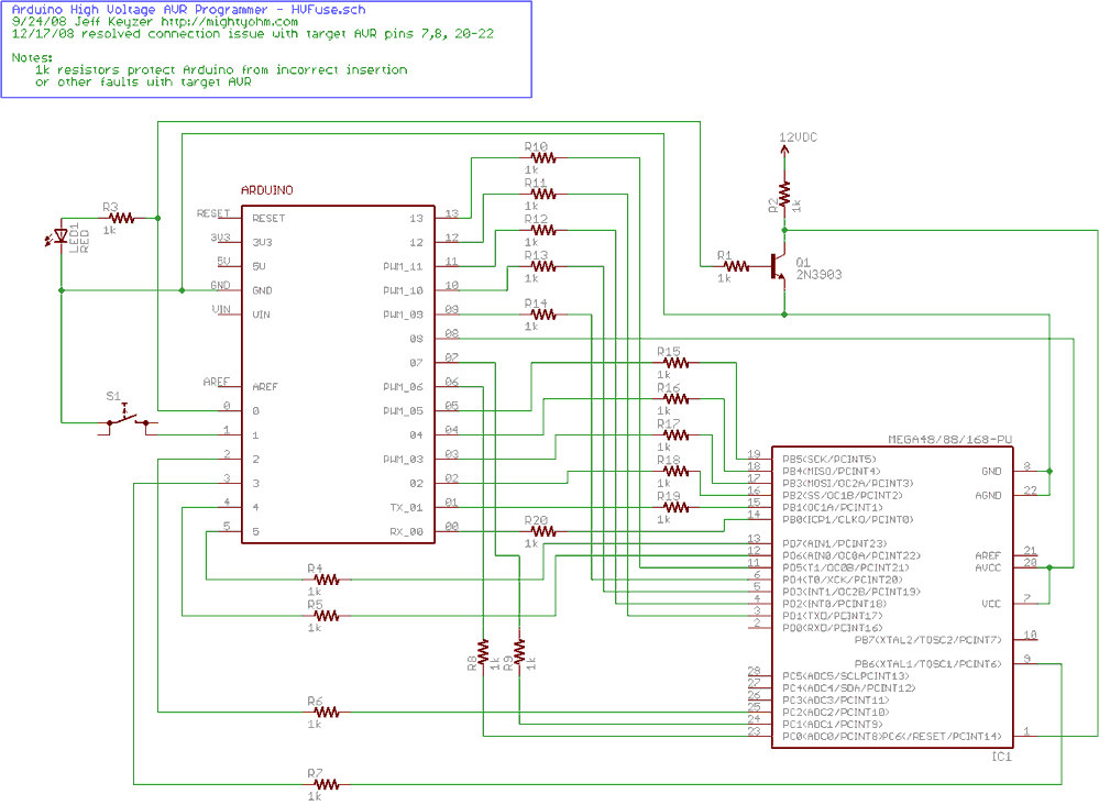
Fortunately, my trusty Arduino came to the rescue. I created an Arduino-based AVR programmer that uses the high voltage programming mode and can fix pesky fuses like RSTDISBL. The Arduino has just enough IO to implement the entire HV...
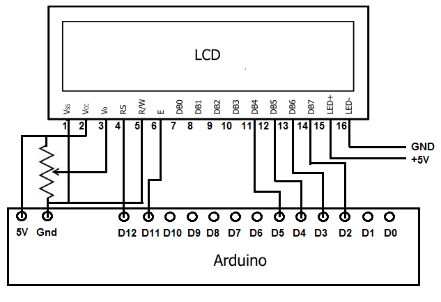
To achieve this, the first step involves establishing the necessary physical connections between the Arduino board and the LCD. Following this, code must be written to display the desired text on the LCD. LCDs have become the standard means...
The SD library integrated into the Arduino IDE has replaced this code. Its only advantage is that it can fit and operate on an ATmega168 Arduino, making it potentially useful for users unable to upgrade. For all other cases,...
This novel buzzer circuit uses a relay in series with a small audio transformer and speaker. When the switch is pressed, the relay will operate via the transformer primary and closed relay contact. As soon as the relay operates...