
Display Text on an HD44780 LCD with an Arduino
A computer is required to write the code that sends text to the Arduino board, which in turn transmits this data to the LCD. A USB cable with Type A and Type B connectors is needed, where the Type A connects to the computer and the Type B connects to the Arduino board, establishing a communication link for code upload. For a comprehensive understanding of the LCD pinout connections, refer to the HD44780 LCD Pinout documentation, which details the function of each pin.
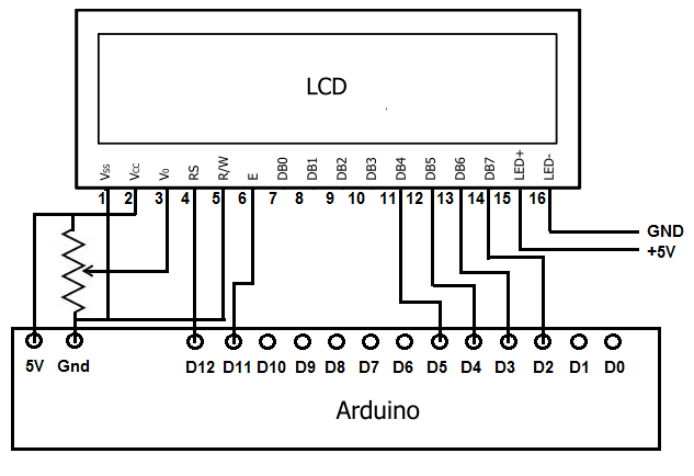
Pins 1 and 2 supply power to the LCD, connecting to the Arduino's 5V and ground pins. Without power, the LCD will not function. Pin 3 adjusts the contrast of the LCD screen, typically connected to a 10kΩ potentiometer, with the wiper terminal connected to pin 3 of the LCD and the other two terminals connected to 5V and ground. Proper adjustment of this potentiometer is crucial, as incorrect settings may result in no visible output.
Pin 4 serves as the register select pin, operating in command mode when LOW (no voltage) and data mode when HIGH (voltage). This pin connects to digital pin D12 on the Arduino. Pin 5 is the read/write (R/W) pin, which also operates in two modes: write mode (LOW) and read mode (HIGH). For this project, it will be permanently connected to ground to ensure write mode operation, although it could be connected to a digital pin for switching between modes.
Pin 6 is the clock enable pin, which must be connected to digital pin D11 on the Arduino to allow instruction processing. Pins 7, 8, 9, and 10 remain unconnected as the HD44780 LCD operates in either 4-bit or 8-bit mode. This project will use 4-bit mode, requiring only four digital pins. Pins 11, 12, 13, and 14 will be connected to Arduino pins D5, D4, D3, and D2, respectively, transmitting the data to the LCD. Pins 15 and 16 control the backlight of the LCD, with pin 15 receiving +5V and pin 16 connected to ground.
Once the physical connections are established, the next step is to write the code that instructs the LCD on what text to display. For instance, the code can be programmed to show the text "Hello there" followed by the elapsed time since the code was uploaded. The code will define the number of rows and columns of the LCD, accommodating various types such as 16x2 or 20x4 configurations. The digital pins used on the Arduino board will be declared, and the loop function will control the cursor's position on the LCD, specifically at column 0, line 1. This setup allows for the display of the message and the elapsed time, demonstrating the circuit's functionality.To do this, first, we must make the appropriate physical connections from the arduino board to the LCD. Then after, we must write the code so that whatever text we want displayed comes up on the LCD. LCDs are pretty much the standard now in order to display text to users of a device. Almost all electronic devices which give a readout to users of s ome type of data use LCDs to do so. This includes CD players, microwaves, thermostats, ovens, all come with LCDs which display some type of readout so that users can obtain some type of data. For thermostats, it`s the temperature. For microwaves, it`s a how much time until it shuts off. For CD players, it`s what track in the CD is currently playing. LCDs are so important in electronics today that learning as much about them is a smart way to keep yourself up with the industry.
So in our project, learning how to write text to LCDs is a great way to eventually learning how to build electronic devices that can display data out to an LCD so that a consumer can obtain the data he or she needs. There are plain text LCDs and graphical LCDs (GLCDs). Graphical LCDs can display fine graphical detail better than text. They are avaiable for a small price premium over text displays. We need a computer to write the code needed to send the text we want to display on the LCD to the arduino board.
The arduino board then transfers this data to the LCD. We need a USB with a type A connector and a type B connector. The type A connector connects into the computer and the type B into the arduino board. Thus, we have a connection between the arduino and the computer, so that we write the code on the computer and then upload it to the arduino. For a more in-depth explanation of the pinout connections to the LCD, see HD44780 LCD Pinout. This will help to explain the pins, and what each does, of the LCD. Basically, pins 1 and 2 give power to the LCD. This is why they connected to the 5V pin and the ground pin of the arduino. Without power, the LCD cannot power up and, thus, display anything. Pin 3 gives contrast to the LCD screen. It normally hooks up to a 10KG potentiometer to pin 3 of the LCD. The wiper terminal (variable portion of the potentiometer) is what hooks up to pin 3. The 2 end terminals of the potentiometer connect to the 5V and ground terminals of the arduino. It doesn`t matter which ends connect to each. One end just has to connect to 5V and the other end connects to ground. By adjusting potentiometer with this setup, we can adjust the contrast of the LCD screen. If this pin is not adjusted properly, a user may see no output at all. So adjusting this until text can be seen if all other connections are made is crucial to the functioning of the LCD.
Pin 4 is the register select pin. This register select pin can be in 1 of 2 modes. If no voltage is given to it (it is LOW), then it is in command mode. If voltage is given to it (it is HIGH), it is in data mode. We connect this pin to the arduino`s (digital) D12 pin. Pin 5 is the R/W, or read/write, pin. This pin, just like the previous one, can be in 1 of 2 modes. If no voltage is given to it (it is LOW), then it is in write mode. If voltage is given to it (it is HIGH), then it is in read mode. If it is in write mode, then we can write text to it so that it can be displayed. When it is in read mode, this is only necessary in rare instances when we want to read what the LCD is displaying. The majority of the time, though, it will be connected in write mode. For simplicity sake, we will only be writing to the LCD, so we will have it permanently connected so that it stays in write mode.
To do this, we connect it to the ground pin of the arduino. Again, this makes it permanently be in write mode. If you want to be able to change it from read to write mode and vice versa, you would connect this to a digital pin. Pin 6 of the LCD is clock enable pin. The HD44780 LCD is an LCD which is run by a clock. It is falling edge triggered so it executes all instructions it receives on the falling edge of each clock cycle.
In order for the LCD to process instructions, the clock must be enabled, so this pin must be connected. We connect this pin to arduino digital pin D11. Pins 7, 8, 9, 10 of the LCD are left unconnected. The HD44780 LCD can run on 1 of 2 modes- 4 bit mode or 8 bit mode. We will use 4 bit mode. When using 4 bit mode, we only have to use 4 digital pins of the LCD. When using 8 bit mode, we have to use 8 digital pins of the LCD. There is a theoretical advantage to using 8 bit mode in terms of the LCD efficiency, but not enough to warrant 4 more connections.
This is why we use 4 bit mode and leaves pins 7, 8, 9, 10 open. Pins 11, 12, 13, 14 are the 4 digital pins of the LCD. These are the digital pins that represent the 4 bits of 4-bit mode. These represent the digital bits of the actual data that we transfer to the LCD. So, for example, when we send text to the LCD so that it`s displayed, these pins transfer that data to the LCD. Pins 11, 12, 13, 14 connect to the arduino board pins D5, D4, D3, D2, respectively. Pins 15 and 16 represents the backlights of the LCD. This is an optional connection. If you want the backlights to be on, then you must power them. Pin 15 is the anode pin. This pin receives the +5V of positive voltage which the LED needs. Pin 16 represents the ground pin. This represents all the wiring that must be done from the arduino board to the LCD. Now all we have to do is write the code (instructions) that the LCD needs to display the text we want it to.
In our example, we display the text, "Hello there" on our LCD, followed by the number of seconds that has elapsed once the code is uploaded. You can change this to whatever text you want shown. Customize to it anything or you can run our code, as is. The second block code declares the number of rows and columns that the LCD that we use has. There are many different types of LCDs, including 16x2 20x4, etc. Here we declare the rows and columns which the LCD has. The third line of coe declares all the digital pins of the arduino board we will be using. On our arduino board, we use its digital pins D12, D11, D5, D4, D3, and D2. These we all declare. The fourth block of code, the loop() function, sets the cursor (or blinker) at column 0, line 1. This is the place on the LCD where we want the cursor to blink on and off from. See the video below to see this circuit in action. It displays the message "Hello there" followed by the number of seconds that has elapsed since the software has been uploaded to the board.
🔗 External reference
Related Circuits
Running Message Display Circuit Diagram. This circuit is based on the CD401 IC. Features: Light emitting diodes are advantageous due to their smaller size. The Running Message Display Circuit utilizes the CD401 integrated circuit, which is a versatile component in...
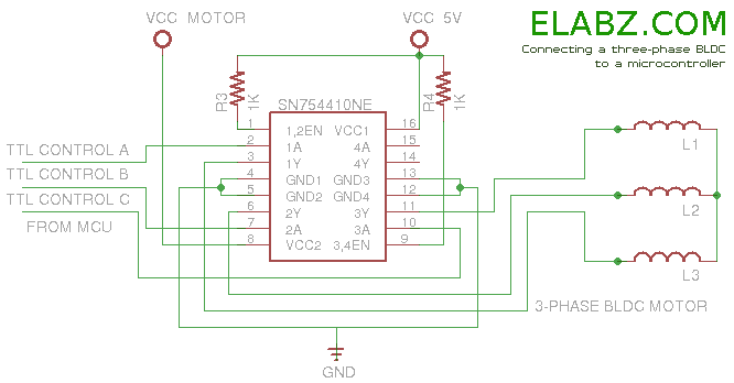
Arduino sketch and other useful information about driving a brushless DC motor, such as a DVD drive spindle motor, using Arduino or another microcontroller. The task of driving a brushless DC motor, particularly one sourced from a DVD drive spindle,...
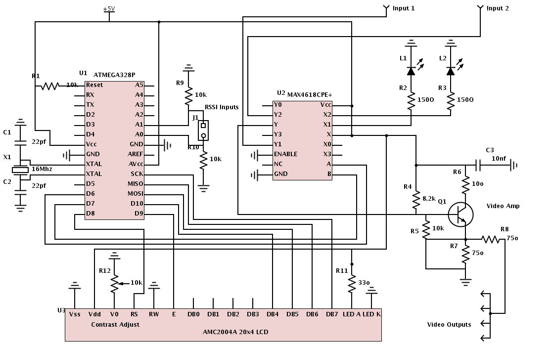
All necessary materials have been gathered to work on an Arduino-powered diversity controller. The design aims to support two inputs, although the hardware can accommodate up to four inputs, and features four amplified outputs. The diversity function will utilize...
LED displays consist of arrays of Light Emitting Diodes (LEDs) arranged in various shapes to convey specific information. The operation of LED displays is similar to that of standard LEDs, requiring straightforward connections when sufficient microcontroller pins are available....
The copyright of this circuit is owned by Smart Kit Electronics. This document discusses improvements and modifications based on the original schematic. It describes a straightforward yet highly accurate and useful digital voltmeter designed as a panel meter, suitable...
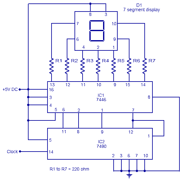
The circuit is based on asynchronous decade counter 7490 (IC2), a 7 segment display (D1), and a seven segment decoder/driver IC 7446 (IC1). The seven segment display consists of 7 LEDs labelled a through g. By forward biasing different...