
Novel Buzzer

The described buzzer circuit operates on a principle of rapid relay switching, which creates an audible tone through the interaction of an audio transformer and a speaker. The circuit is initiated when a switch is pressed, allowing current to flow and energizing the relay coil. This action closes the relay contacts, completing the circuit to the audio transformer.
The audio transformer, designed to convert the low voltage signal from the relay into a higher voltage signal, plays a crucial role in generating sound. As the relay operates, the normally closed contact opens, which interrupts the current flow to the relay coil. This interruption causes the relay to disengage, which in turn closes the contacts again, re-energizing the coil and restarting the cycle. This rapid on-off switching creates a series of pulses that resonate within the transformer, producing sound waves through the connected speaker.
The frequency of the relay's operation directly influences the pitch of the sound emitted by the speaker. The fluctuations in the current through the primary winding of the transformer induce corresponding fluctuations in the secondary winding, which drives the speaker. The use of a capacitor (labeled as C in the circuit) allows for tuning the frequency of the relay's operation, thereby adjusting the tone produced. The nominal value of this capacitor can be selected based on the desired frequency characteristics and sound quality.
In summary, this buzzer circuit exemplifies a simple yet effective method of sound generation through electromagnetic relay action, transformer coupling, and capacitive tuning, making it suitable for various applications where audible alerts or sound signals are required.This novel buzzer circuit uses a relay in series with a small audio transformer and speaker. When the switch is pressed, the relay will operate via the transformer primary and closed relay contact. As soon as the relay operates the normally closed contact will open, removing power from the relay, the contacts close and the sequence repeats, all very quickly...
..so fast that the pulse of current causes fluctuations in the transformer primary, and hence secondary. The speakers tone is thus proportional to relay operating frequency. The capacitor C can be used to "tune" the note. The nominal value is 0. 🔗 External reference
Related Circuits

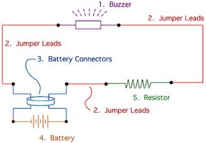
This project involves creating a simple buzzer circuit that allows for volume control of the sound output. The volume can be adjusted using a potentiometer. When the potentiometer is set to a low resistance (near 0Ω), the buzzer produces...
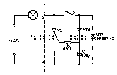
Closing the switch S allows the AC positive half-cycle to flow through diode VDI and resistor R, causing the SCR to open simultaneously at both ends of the capacitor C, which becomes fully charged. During this phase, the positive...
A quiz buzzer circuit is designed to output to a basic piezoelectric buzzer. The quiz buzzer circuit functions as a simple and effective signaling device, commonly used in quiz competitions and games to indicate responses or correct answers. The primary...
The drive circuit is a basic drive recently designed to accommodate a 27mm passive piezoelectric buzzer, aiming for a sound output exceeding 100dB while minimizing power consumption. Due to constraints related to product cost and structural size, the circuit...
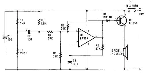
This electronic door buzzer circuit schematic has a straightforward function and is simple to construct. The circuit employs an LF351 operational amplifier along with a few common electronic components. When the S1 push-button is pressed, a positive voltage is...
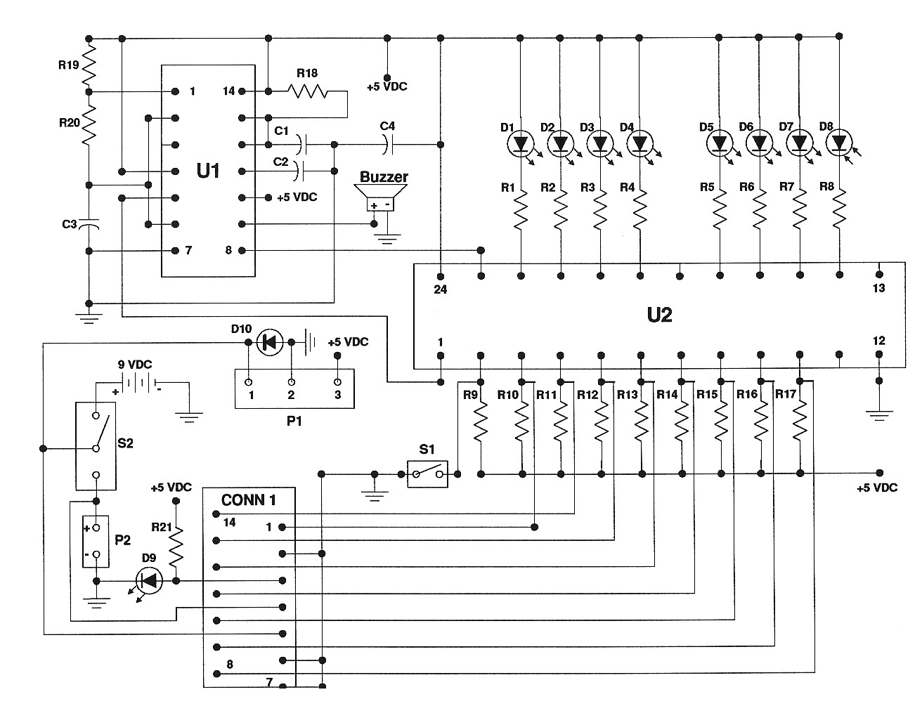
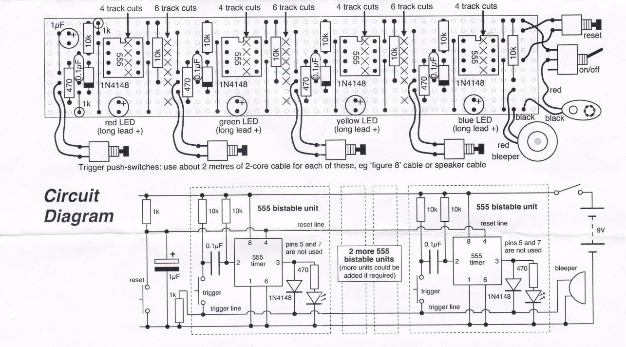
Building a competition buzzer set involves the construction of a contest buzzer system. The kit includes an etched, undrilled printed circuit board, a programmed PLD, a 556 timer, various mounting hardware, and a detailed assembly manual. The kit is...