
Arduino Calibration

The described circuit involves an Arduino microcontroller configured to calibrate sensor inputs effectively. During the initialization phase, the system collects analog readings from a photocell, also known as a light-dependent resistor (LDR), for five seconds. This time frame allows the Arduino to establish baseline values for environmental light conditions. The highest and lowest readings recorded during this period set the thresholds for subsequent readings in the main loop of the program.
To implement this circuit, an LED is connected to digital pin 9 of the Arduino through a 220-ohm resistor, which serves to limit the current and protect the LED from excessive voltage. The photocell is connected in a voltage divider configuration with a 10K-ohm resistor. One terminal of the photocell is connected to the 5V power supply from the Arduino, and the other terminal connects to analog pin 0, which reads the voltage across the photocell and the resistor combination. The other end of the 10K-ohm resistor is grounded, completing the circuit.
In operation, the Arduino continuously monitors the voltage at analog pin 0. During the initial five seconds, the program compares each reading against the established minimum and maximum values. If a reading falls below the minimum, it updates the minimum threshold; conversely, if a reading exceeds the maximum, it updates the maximum threshold. This calibration process allows the system to adapt to varying lighting conditions, ensuring accurate sensor readings throughout its operation.
This configuration is beneficial in applications where precise light measurements are critical, such as in automatic lighting systems or environmental monitoring setups. The use of a photocell allows the circuit to respond dynamically to changes in ambient light, while the LED provides visual feedback or can serve as an indicator for system status or alerts.This example demonstrates one techinque for calibrating sensor input. The Arduino takes sensor readings for five seconds during the startup, and tracks the highest and lowest values it gets. These sensor readings during the first five seconds of the sketch execution define the minimum and maximum of expected values for the readings taken during th
e loop. Connect an LED to digital pin 9 with a 220 ohm current limiting resistor. Connect a photocell to 5V and then to analog pin 0 with a 10K ohm resistor as a reference to ground. These may seem backwards. Initially, you set the minimum high and read for anything lower than that, saving it as the new minimum. Likewise, you set the maximum low and read for anything higher as the new maximum, like so: 🔗 External reference
Related Circuits
DAC stands for Digital to Analog Converter. This article explores the code created by Michael Smith for a PWM-based DAC. The code has been modified to allow for the testing of various DAC options. A comparison is made between...
Make your own Guitar Effects Pedal with an Arduino board. Bit crushing, rate reducing, weird noises. 10-bit effects/guitar pedal with an Arduino for lo-fi DSP The project involves designing a guitar effects pedal utilizing an Arduino microcontroller to create various...
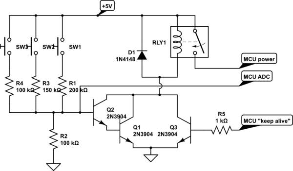
A circuit is being designed that utilizes a combination of switches and resistors to enable a microcontroller to identify which switch has been pressed based on the voltage read, and subsequently perform a switch-specific action. The proposed design incorporates...
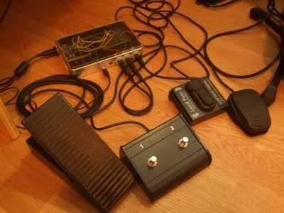
Build a Guitar Looper with an Arduino board. Here is how to produce a pedalboard for electric guitar. The idea is to connect pedals to the Arduino and to use them to control a software of sound processing in...
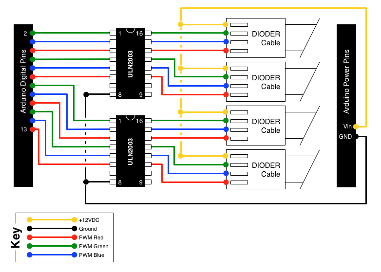
A few weeks ago, it was noted that IKEA offers a set of color-changeable LED strips. There has been a search for an effective method to provide... The color-changeable LED strips from IKEA are designed to offer flexibility in lighting...
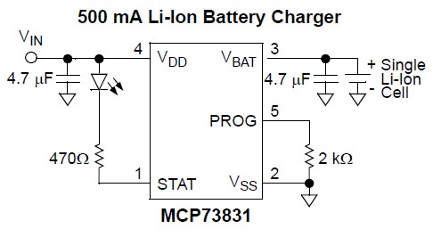
A Lithium Polymer Ion Battery is included with the Lilypad Development Board from SparkFun. There is an inquiry regarding whether the battery will charge when it is connected to the Lilypad Arduino while simultaneously connecting the Lilypad Arduino using...