
arduino Switch transistor with a low voltage and current
The circuit design involves a microcontroller, such as an Arduino, that interfaces with multiple switches through a resistive voltage divider. Each switch is connected to a resistor, creating a unique voltage level for each switch press. This voltage is read by an analog input pin on the microcontroller, allowing it to determine which switch has been activated based on the voltage level.
The relay activation is controlled by a transistor, which acts as a switch for the relay coil. To ensure that the transistor is activated properly, a low-side N-channel MOSFET is recommended. The gate of this MOSFET will be connected to the microcontroller's output pin and also to a pull-down resistor to ensure it remains off when not activated. The switch will pull the gate voltage high when pressed, turning on the MOSFET and allowing current to flow through the relay coil.
The circuit should also include a current-limiting resistor connected to the digital output pin of the microcontroller. This resistor ensures that the current flowing into the gate of the MOSFET does not exceed the maximum rating of the microcontroller pin, while still being low enough to not interfere with the switch operation.
The use of a relay in this design is justified due to the need to control a higher voltage or current load, but care must be taken to select a relay with a coil current that is compatible with the output capabilities of the microcontroller. If the relay coil requires more current than the microcontroller can provide, an additional driver circuit may be necessary.
To enhance battery life, it is crucial to implement low-power techniques. The microcontroller can be programmed to enter a low-power sleep mode when inactive, significantly reducing power consumption. The resistive ladder design should be optimized to ensure that the microcontroller can wake up reliably without drawing excessive current.
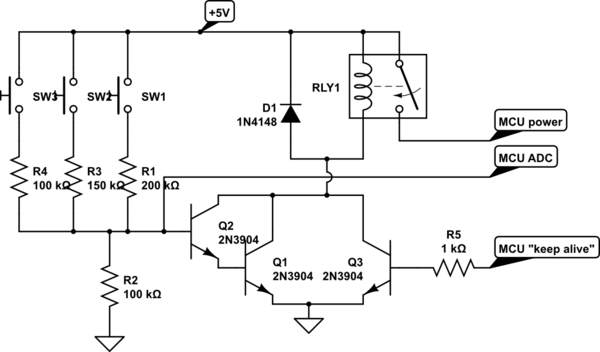
In summary, the circuit design aims to create an efficient, low-power system that utilizes a combination of switches, resistors, and a transistor to control a relay, thereby powering a microcontroller for specific actions based on user input. The design must address current limitations and ensure reliable operation while maximizing battery longevity.Designing a circuit that will use a combination of switches and resistors to allow a microcontroller to identify which switch was pressed based on the voltage read and perform a switch-specific action. The design that I`ve come up with involves using a transistor to activate a relay, which powers the microcontroller.
When the microcontroller is powered, it pulls a pin high to take over powering the relay. When the action is finished the microcontroller pulls the pin low, deactivating the relay and cutting power to the microcontroller. I`ve tested the circuit with one switch and a voltage divider to simulate the largest resistor/lowest voltage combination from my switch array.
The voltage that I`ve calculated at the transistor is 1. 6 V, and the current is 0. 017 mA. The high resistor values are necessary since I need approximately 0. 2 V differential between switches. The problem is that the transistor is not being activated (it works if I feed it 5V directly). My question: Is this because the current is too low How would I go about rectifying this (other than decreasing resistances) If there is a better approach to this problem, I`d love to hear it also. This is a circuit for a picture frame that will do specific actions depending on the button that is pressed.
This will be battery-operated using 6 D-cell batteries, mounted on the wall. I`d like to get months if not years of operation out of it before having to replace the unit. My Arduino with an attached shield (with using a MAX667 power supply rather than the stock one) consumes 45 mA at low power. The stock Arduino doesn`t go into low power mode although with a programmer the chip can be modified to go into low power mode and consume nA of current.
At 45 mA, the batteries will last about 11 days (266 hours for a 12000 mAh battery). Hence the requirement that the resistive ladder turn on the device. It`s a bit heath-robinson, all this. does it offer much real benefit over a low-power microcontroller which is always powered but in sleep most of the time pjc50 May 17 `13 at 19:23 @pjc50 What have you got against Mr Robinson`s fine products :-). | The problems are more to do with the implementation. Properly done this can have advantages and cost very little. Relay should be a MOSFET. Kurt`s cct is going in the right direction and is OK as an example BUT the low side switch and hi floating processor will easily cause problems.
Putting the MOSFET on the high side and using a switch operated jellybean BJT or another FET to operate the high side FET is most of what`s needed. Drain can be so close to true zero as is unmeasureable. Russell McMahon May 17 `13 at 20:51 There`s another problem, too: The current out of an Arduino will not be sufficient to drive the coil of a relay, as the typical spec is 25 mA per pin out, and typical relays use 35-100 mA of current for their coils.
I question your assumption, though: What is the "0. 2V" that you need for the switch What do you think that means Where does this number come from Specifically, when the switch is open, the voltage gap across the switch will be pretty much VCC, as the switch resistance will be close to infinite. When the switch is closed, the voltage across the switch will be close to zero, as the switch will have close to zero resistance.
There are various solutions to the core problem of "how to turn on a microcontroller with a button, and then keep it on until it`s done. " You might use a low-side N-channel MOSFET to switch on the relay coil. There would be a pull-down on the MOSFET gate, and the switch would pull it up to VCC. The digital out of the MCU would also be connected to this MOSFET gate, with a current limiting resistor that`s lower than the pull-down, but high enough to not interfere with the switch when low.
I`d suggest 10 kOhm for the pull-down, and 1 kOhm for the digital pin resistor, and the switch goes straight from the MOSFET gate to V 🔗 External reference
Related Circuits
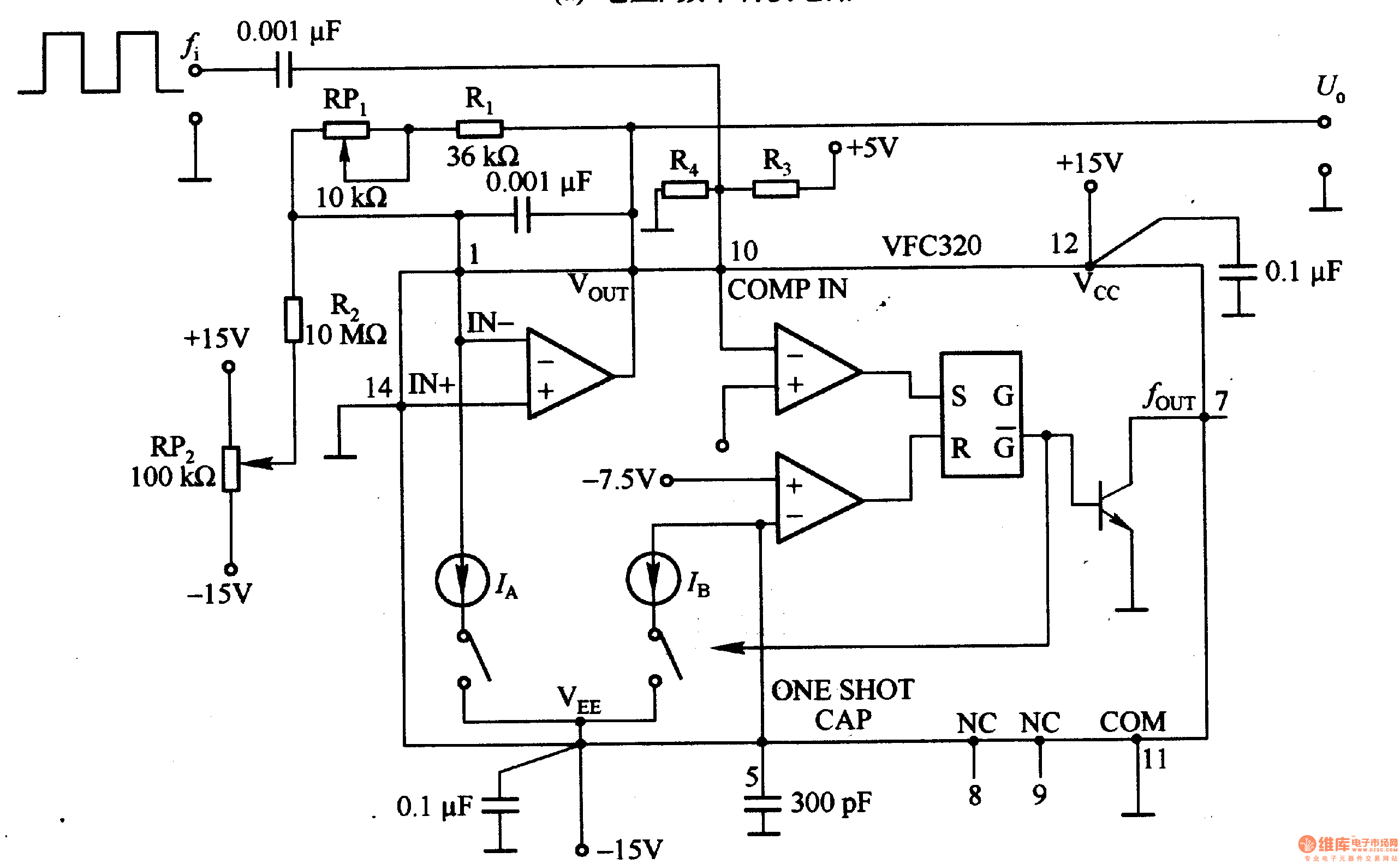
Figure 1-22 (a) illustrates a circuit that converts an input voltage of 0 to +10V (Ui) into a pulse with an output frequency ranging from 0 to 100kHz. In this configuration, pin 7 of the VFC320 is connected to...
This line-following robot sensor, also known as a surface scanner for robots, is a compact, stamp-sized infrared proximity detector designed for short-range detection, typically within 5 to 10 mm. The line-following robot sensor operates using infrared light to detect the...
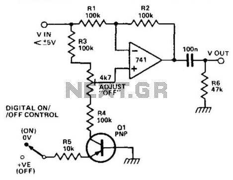
When transistor Q1 is switched off, the circuit operates as a voltage follower. By applying a positive voltage to the emitter of Q1 through a 10 kΩ resistor, the transistor is activated and enters saturation. Consequently, the lower end...
This design was created to address a challenge with the tailwheel doors of the P-51 Mustang. The issue arises from the complex undercarriage sequence, which would necessitate two independent sequencers. The closing sequence involves the main gear doors opening,...
The circuit detects the mains current supplied to a master device and controls the on/off state of slave equipment. This functionality is particularly beneficial in environments such as hi-fi systems or home computers, where multiple peripheral devices can be...
The supply of circuit becomes from a AC line in the J1. This voltage can be from a separate transformer 2X12V (the prices of materials that I give it is for 2X12V AC), from existing coil 12V in their...