
arduino circuit
The circuit described involves integrating an RFID reader with an Arduino microcontroller to create a basic access control system. The Innovations ID-20 RFID reader is connected to the Arduino via a breakout board, which simplifies the connection process by providing clearly labeled pins for power, ground, and data transmission. The reader operates at a frequency of 125 kHz and is capable of reading RFID tags within a specific range, depending on the model used.
For the wiring setup, the VCC pin of the RFID reader is connected to the 5V output of the Arduino, while the ground pin is connected to the Arduino's ground. The data output pin from the RFID reader is connected to a designated digital I/O pin on the Arduino, allowing it to receive signals when an RFID tag is presented to the reader.
The Arduino is programmed to monitor the data pin for incoming signals. When an RFID tag is detected, the Arduino processes the tag's unique identifier and can execute specific actions, such as unlocking a door or activating an LED. The program logic includes conditionals to check for specific tags, enabling versatile control based on which tag is read.
In addition to the basic functionality, future enhancements may include the integration of additional sensors or outputs, such as a relay to control a door lock mechanism or an LCD display to provide user feedback. The choice of components, such as resistors or transistors for driving LEDs, should be based on the specifications of the components used to ensure reliable operation and prevent damage to the Arduino or RFID reader.
Overall, this setup provides a foundational understanding of how to implement RFID technology in a practical application, with room for expansion and customization based on user needs.This page is browser friendly, by the way. Make your browser`s window less wide than your whole screen and you will find the narrower columns much easier to read. The page is in two parts. At the top, there`s a very basic program, showing you the RFID reader at work. At the bottom, that program is slightly modified, to create something to open a d oor when either of two specific RFID devices are brought near the reader. Before we get down to work, how`s this for a neat way to carry an RFID tag with you everyday The central photo shows the tag. It is a small glass capsule. Sparkfun sell them in this form for about $5. My watch strap just happens to have a little cavity, just the perfect size, on its underside. I`m still looking for the "perfect" glue to hold it in place. Hot-melt glue wasn`t the answer. In this page I will show you the basics of connecting an Innovations ID-20 RFID reader, available from Sparkfun.
com, to an Arduino. ($35, (+p&p, 12/11)While the essay was written while working with an ID-20, I don`t believe that users of the ID-12 would do anything different. (The ID-12 is less expensive, $30, (+p&p, 12/11) but doesn`t read over such a long range. In hindsight, I don`t thing the extra range of the ID-20 makes any difference to me, in my application.
I have the ID-20 behind a pane of glass, and "wipe" my RFID tag across the glass. I don`t think the ID-12 would have trouble. I have to bring my tag within about 8cm of the reader anyway, so being closer isn`t a problem. See below for an even less expensive option. ) If you take my advice, if you buy the Sparkfun product, you will also buy the breakout board Sparkfun offers for the ID-20 (or ID-12). Part SEN-08423, 95 cents. And the 2mm socket strip (2x PRT-08272, $1 ea). The pin numbers used below are the pins as numbered on that. After I`d built one instance of my RFID access control solution, I encountered a different source for a reader.
$11 (+p&p, Dec 11). to go at the heart of it, ITeadStudio. com. The link will take you to their storefront. Use the menu at the left to drill down to their RFID section. You want the "125Khz RFID module RDM6300 - UART". note the "UART" part. (I actually used the older RDM630, but the site says the 6300 works the same way, only better(!). The ITeadStudio module is less expensive, but also less well packaged. The illustrations on the websites are fair. It is also less sensitive. The tag that the ID-20 read at 8cm has to be within 2cm. still no problem for my wants. The software presented here works fine with either reader, without tweaks. I`ve bought 125mHz tags from Sparkfun, from ITeadStudio, and from an eBay source. all work fine with either reader. ITeadStudio has some nice 28mm "key fob" tags, and they don`t emblazon their logo across their product. Speaking of eBay. in addition to the tags I did receive. I saw some tags on eBay at a "too good to be true" price. and it was. Despite sending $3. 98 by PayPal (Aug 11) to xiao2huan for something very like item 150632480332 (Dec 11), and a civil exchange of emails, no tags ever arrived, not the first shipment, not promised replacement.
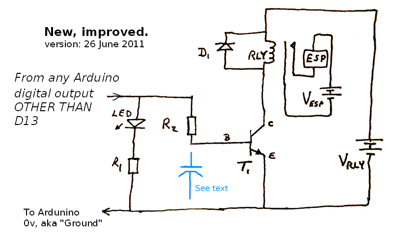
Have you ever tried to "work with" eBay when there`s a problem For a start, I can no longer call up the item description to see how the seller was listed. (Seller names and PayPal accounts are often different, sometimes for good reasons. ) There is a price for everything. I often get good deals via eBay. but it is not unknown to be out of pocket. The "price" for the other times. Pin 2: Connect to 5v for now. But make it easy to move that to one of the Arduino`s digital i/o pins, so you can do the "fancy" version later.
(To be explained in an edition of this page to be created someday in the future!) That`s about it! In the data sheet you will read that pin 10 is an output which, properly connected (at least a resistor. probably transistor plus resistor) can drive an LED, which will light 🔗 External reference
Related Circuits

Conducting pipe rechargeable long delay control circuit. An adjustment potentiometer RP can delay up to several tens of seconds. The conducting pipe rechargeable long delay control circuit is designed to manage the timing of electrical signals, allowing for a delay...

The circuit features grounds ISO122/124 and PGA102, with ISO150 forming a gain programmable channel isolation circuit. The input signal VIN is amplified by the instrumentation amplifier PGA102 to ISO122P, which then outputs VOUT from the isolation amplifier ISO102P. Two...
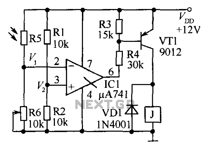
The circuit functions as a precision bright light control circuit, operating independently of power supply voltage and ambient temperature. Resistors R1, R2, R6, and the photosensitive resistor R5 form a two-arm Wheatstone bridge. The precision bright light control circuit utilizes...

Each trigger input can produce a fixed number of pulses, with the range being from 2 to 30. The specific number is determined by the frequency-controlled settings of 1 megohm. A monostable gated unsteady power supply circuit can be...
The circuit diagram for a dynamic toy that produces eight sounds and five flashing lights is illustrated. It features the HFC3018 module, capable of generating eight distinct sounds, including step gunfire, aviation gunfire, game sight, telephone sight, bomb 1,...
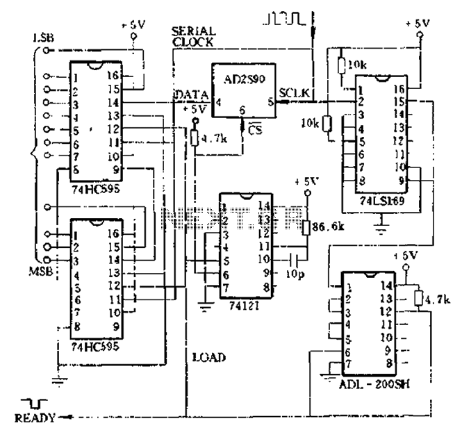
Absolute shaft angle data serial-parallel conversion: the serial AD2S90 axis angle data is converted to parallel data. This method utilizes timed digital pulse signals that can be generated by a microprocessor or a hardware circuit. An example of using...