
ISO122 / 124 and PGA102, isolated channel has a programmable gain circuit diagram
The described circuit integrates multiple components to achieve programmable gain and signal isolation, making it suitable for sensitive applications where noise immunity is crucial. The ISO122 and ISO124 are precision isolation amplifiers that provide high voltage isolation while maintaining signal integrity. These amplifiers are particularly useful in applications where ground loops or common-mode voltages can distort the signal.
The PGA102 is a programmable gain amplifier that allows for precise gain settings, which can be adjusted via digital control signals A0 and A1. This flexibility enables the circuit to adapt to various signal levels, ensuring optimal performance across a range of input conditions. The gain options of 1, 10, or 100 allow for versatility in applications, accommodating both low-level and higher-level signals.
The isolation provided by ISO150 enhances the circuit's robustness against electromagnetic interference (EMI) and radio frequency interference (RFI), which are common challenges in electronic systems. By isolating the input from the output, the circuit minimizes the risk of noise coupling, thus preserving the fidelity of the amplified signal.
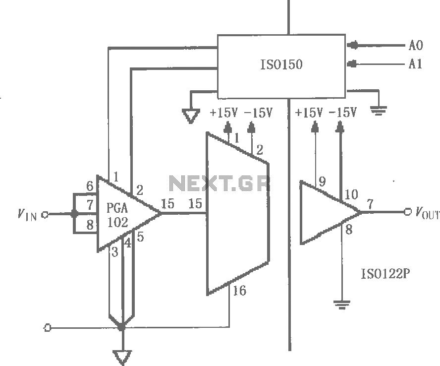
In summary, this circuit design effectively combines gain programmability with high-performance isolation, making it well-suited for precision measurement systems, medical instrumentation, and industrial applications where signal integrity and noise immunity are paramount. The careful arrangement of components ensures that the circuit operates reliably under varying environmental conditions and input signal characteristics.As shown in FIG grounds ISO122 / 124 and PGA102, ISO150 constituted with a gain programmable channel isolation circuit. After the input signal VIN is amplified by instrumentation amplifier PGA102 to ISO122P, after ISO102P isolation amplifier output VOUT. Two gain selection signals A0, A1 by the isolation after ISO150 added PGA102, PGA102 gain is set to (1, 10 or 100).
Because the signal, power, ground and the output of the input signal, power, ground and gain control select pin completely isolated, so a good anti-interference performance of the circuit.
Related Circuits
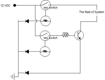
A circuit is being designed that incorporates two key switches, which must both be closed for current to flow through the circuit. The proposed circuit configuration employs two key switches connected in series. In this arrangement, the current can only...
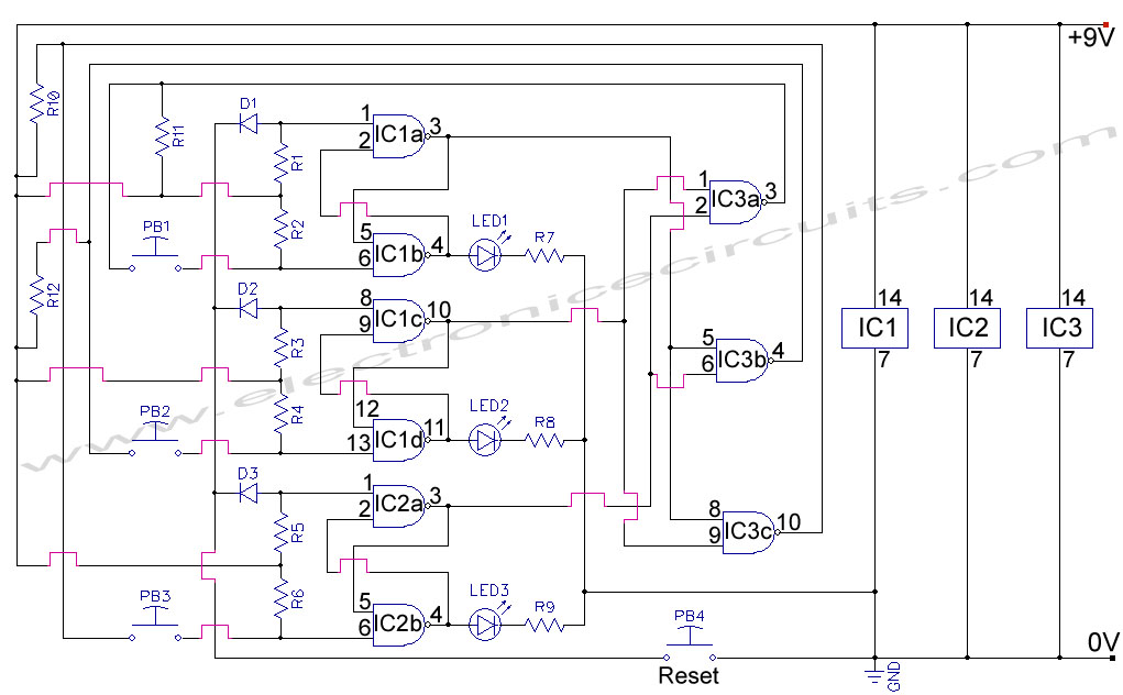
First Response Monitor, Input Selector, Game Circuit. This circuit is utilized for first response applications as it aids in monitoring various responses in games. The First Response Monitor circuit is designed to facilitate real-time monitoring and selection of input signals...
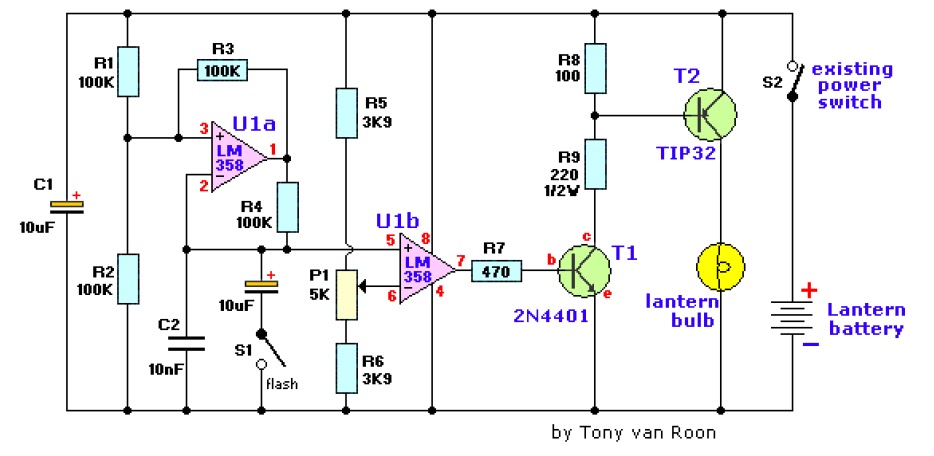
The electronic lantern control circuit enhances an existing battery-powered lantern or flashlight, or can be incorporated into a custom design, by providing high-efficiency dimming and flashing capabilities. This circuit is particularly useful in automotive applications, serving as an effective...
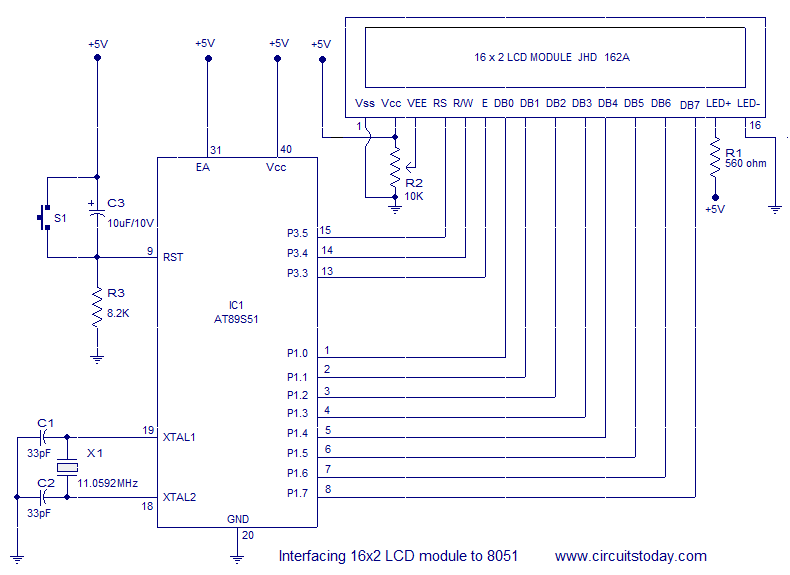
Interfacing a 16x2 alphanumeric LCD module with the AT89S51 microcontroller. The circuit diagram, theory, and program are included. JHD162 LCD module pinout and commands are provided. The integration of a 16x2 alphanumeric LCD module with the AT89S51 microcontroller involves several...
Another method that helps program development besides a dot LED as the output device is a serial bit. With a serial transmission to a terminal emulator program, developer may then test program running easier than a dot LED. One...

Here is a design circuit for a frequency modulator that is equipped with a tuning circuit. In this circuit, a pair of 1N4007 diodes is utilized as varactor diodes. The choice of 1N4007 diodes is not due to their...
Warning: include(partials/cookie-banner.php): Failed to open stream: Permission denied in /var/www/html/nextgr/view-circuit.php on line 713
Warning: include(): Failed opening 'partials/cookie-banner.php' for inclusion (include_path='.:/usr/share/php') in /var/www/html/nextgr/view-circuit.php on line 713