
Trigger multivibrator circuit diagram

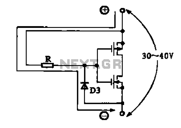
The described circuit utilizes a CD4001, which is a quad two-input NOR gate integrated circuit, to create a monostable multivibrator configuration. This configuration is capable of generating a specific number of output pulses in response to each trigger input. The pulse count can be adjusted between 2 and 30, depending on the resistor-capacitor (RC) time constant, which is influenced by a 1 megohm resistor in conjunction with a capacitor.
When a trigger signal is applied to the input of the monostable circuit, the output transitions from a low state to a high state for a duration determined by the RC time constant. The output pulse width can be calculated using the formula:
\[ T = 0.7 \times R \times C \]
where \( T \) is the output pulse duration, \( R \) is the resistance in ohms, and \( C \) is the capacitance in farads. By selecting different capacitor values, the pulse width can be finely tuned to achieve the desired number of pulses.
The circuit may also include additional components such as diodes for clamping or protection, as well as capacitors for filtering purposes. The output of the CD4001 can be connected to other digital logic circuits or used to drive loads, depending on the requirements of the application.
Overall, this monostable gated unsteady power supply circuit offers a versatile solution for generating precise pulse sequences controlled by a simple trigger input.Each trigger input can produce a fixed number of pulses, the number ranges from 2 to 30, the specific number is determined by the frequency-controlled settings of 1 megohm. Mon ostable gated unsteady power supply circuit, just a CD4001 integrated circuit can be achieved.
Related Circuits
Due to the varying conditions of different input signals, when an abnormal voltage is applied to the pin, protection circuits are established to create a circuit path from the LSI (large scale integration) circuits for internal protection. The structure...
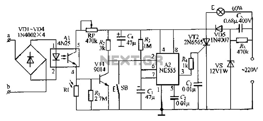
The lamp base circuit integrates an NE555 timer and optocouplers to automatically activate the light when a phone call is received at night. The lamp will self-extinguish after a delay. Additionally, a switch allows manual control of the lamp....
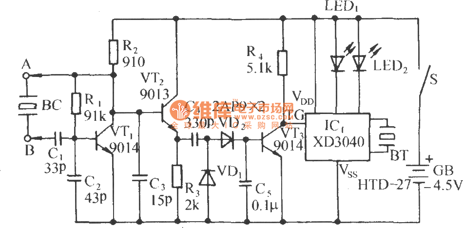
The circuit consists of a capacitance three-point oscillator, an isolation level, a voltage doubler rectifier circuit, a stereo sound circuit, and a flash display circuit. It can detect the quality of a crystal; a good crystal will emit a...
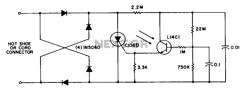
This circuit is utilized for remote photographic flash units that synchronize with the flash attached to the camera. It is designed to connect to the trigger cord or hot shoe of a commercial portable flash unit, allowing the unit...
This simple stereo encoder circuit schematic is built with two ICs, MMC4066E and MMC4047, along with one transistor, BC547B. The audio output is taken from pins 2 and 3 of IC1. The stereo encoder circuit utilizes the MMC4066E, which is...
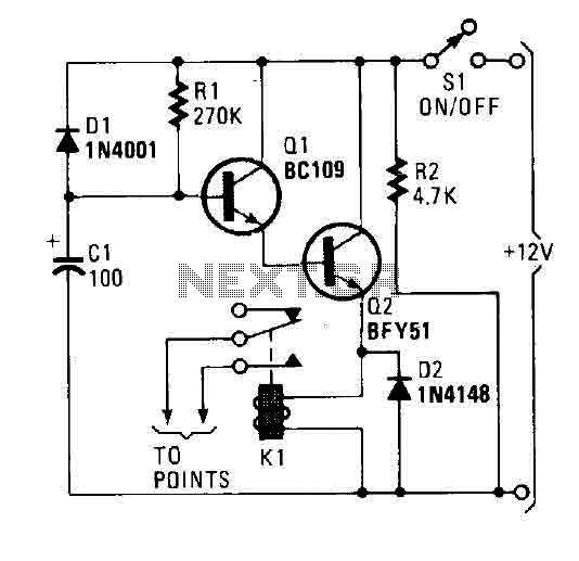
A flip of 51 activates the system. Power for the circuit is derived from the ignition switch, and the circuit receives no power until the ignition switch is closed. When the camera is powered on, capacitor C1 is charged,...