
arduino clock
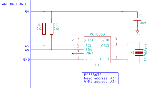
The project centers around using an Arduino microcontroller in conjunction with a PCF8563 real-time clock (RTC) IC to display and manage time and date information. The PCF8563 IC is designed to maintain accurate timekeeping and date management, even when the Arduino is powered off, through the use of an optional battery backup. The integration of an LCD display allows for a user-friendly interface, enabling real-time visibility of the clock's output.
The circuit setup involves connecting the PCF8563 to the Arduino, typically via I2C communication, which requires only two wires (SDA and SCL) in addition to power and ground connections. The 8-pin DIP package of the PCF8563 makes it straightforward to integrate into breadboard or PCB layouts. The optional battery connection is critical for maintaining time accuracy during power outages, as it supplies the necessary voltage to the RTC chip.
In terms of software, the Arduino IDE is used to upload a sketch that manages the timekeeping functions and handles user inputs via the serial monitor. The sketch includes routines for initializing the RTC, reading the current time and date, and allowing the user to set or modify these values through a defined menu system in the serial monitor.
The user interaction through the serial monitor is designed to be intuitive, prompting for input and guiding the user through the process of setting the time and date. The requirement for two-digit inputs ensures consistency in data entry, which is essential for maintaining the integrity of the timekeeping function.
Overall, this project serves as an excellent introduction to interfacing microcontrollers with real-time clock modules and LCD displays, while also providing practical experience in programming and circuit design. The potential troubleshooting steps and community support avenues offer additional resources for users who may encounter difficulties during implementation.The Arduino displays the time and date on a LCD (optional) and in the Arduino IDE serial monitor window. A PCF8563 real time clock (RTC) IC is used to generate the time and date. The time and date can be set using the Arduino serial monitor window. An optional battery can be used to back up the time and date settings in the realtime clock chip so that the time and date are not lost if the
Arduino power is unplugged. Preferably you should follow all the beginner tutorials in order, but as a minimum: if using a LCD display, complete Tutorial 12: Arduino LCD. You should know how to use an 8 pin IC, e. g. from tutorial 5. Two circuit diagrams are shown. The first shows only the RTC chip (PCF8563) connected to the Arduino. The second circuit diagram shows the optional battery backup added. To add the LCD, follow tutorial 12. First interface the PCF8563 to the Arduino as shown in the first circuit diagram above. The PCF8563 is packaged in an 8 pin DIP (Dual In-line Package). The circuit can then be tested using the Arduino IDE serial monitor window as explained in the sections below.
The clock sketch is too long to list here, so download the clock. zip file that contains the Arduino sketch for this project. Copy the clock folder from the zipped file to your Arduino sketchbook folder. Alternatively, copy the text from the enclosed file and paste it into the Arduino IDE. Verify and upload the clock sketch to the Arduino. If a LCD is interfaced to the Arduino and the clock sketch is loaded, the time and date should be displayed on the LCD immediately. Open the Arduino serial monitor window to see the time and date displayed and updated every second. The time and date can be set as described below. When the Arduino serial monitor window is open, the time and date can be set by sending `s` to the Arduino.
The image below shows the menu that is displayed in the serial monitor window after sending the `s` character. After the menu is showing, select what you want to change from the menu. E. g. to change the hour value of the time, send `4` and you will be prompted to send the new time. Always send two numbers for any setting, i. e. don`t send 2 to set the hour to 2, send 02. Change as many parameters as you want and then send `7` to write all the changes in one go. Some people are experiencing problems with this tutorial. This tutorial seems to work on some hardware, but not on others this problem still needs to be resolved.
If you are having trouble with getting the sketch to work then go to the Testing the PCF8563 Real Time Clock IC using Arduino article to do some testing / fault finding. Go to the Blog entry for this article for help and to report any problems. 🔗 External reference
Related Circuits
A single beautiful giant ZM1042 NIXIE tube was acquired from Jim Oostveen, leading to the idea of constructing a single-digit NIXIE clock for Geert. The ideal case for this clock was found at a local IKEA store: a wooden...
This evening, after returning home from a paragliding appointment, there was a realization that the RGB LED driver code written the previous day needed improvement. The code was refined and annotated extensively for educational purposes. Although the current skill...
The WWVB signal is broadcast as a 60 kHz carrier that is AM modulated with a time code frame that is updated once per minute. The data rate is one bit per second. Along with time code information, the...
This project replaces the electronics in a standard quartz wall clock with a circuit that uses GPS satellites to obtain precise time. The proposed project involves the modification of a conventional quartz wall clock by integrating a GPS-based timing circuit....
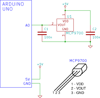
The Arduino reads temperature from an MCP9700 temperature sensor IC and displays the temperature in the Arduino IDE serial monitor window. The circuit utilizes an Arduino microcontroller along with an MCP9700 temperature sensor integrated circuit (IC) to measure ambient temperature....
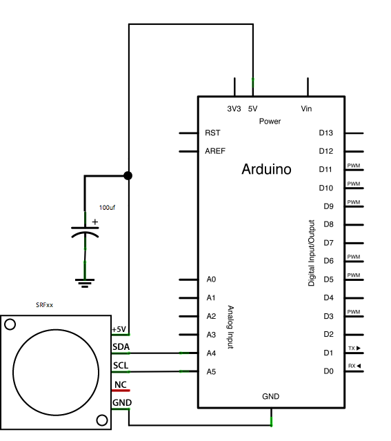
This example demonstrates how to read a Devantech SRFxx, an ultrasonic range finder that communicates via the I2C synchronous serial protocol, using Arduino's Wire Library. The I2C protocol utilizes two wires for data transmission: a serial clock pin (SCL)...