
PIC clock

Construction
Two versions of this clock have been constructed: one utilizing point-to-point wiring and another using a printed circuit board (PCB). Both configurations demonstrate reliable performance. It is essential to position the receiver away from noise sources and to keep wire or trace lengths short to minimize inductance. The receiver is sensitive to magnetic fields generated by power supplies, which can interfere with its operation. A 9V, 200 mA wall adapter was employed instead of an internal power supply to mitigate this issue.
The PCB was designed using Free PCB software (www.freepcb.com). The layout integrates both the main board and the display board into a single design, reducing the cost associated with producing two separate boards. The PCB was manufactured by sending the Gerber files to www.4pcb.com, utilizing their "bare-bones" process, which excludes solder mask and silk-screen printing. The display board can be detached from the main board and mounted at a right angle, with connections made using the provided pads.
This clock receives time broadcasts from the WWVB transmitter located in Fort Collins, CO, and automatically synchronizes its internal time with the WWVB time. It maintains local time even when the WWVB signal is lost. This specific version is configured for Pacific Standard Time and automatically detects and corrects for Daylight Saving Time. The time is displayed in a 12-hour format using a 6-digit display comprised of 1" seven-segment LED displays. An indicator for WWVB synchronization is also included. The core of the system is the PIC 16F628 microcontroller, with software written in C. All necessary tools, including schematic editors, C compilers, PCB layout software, and PIC programmers, are freely available for download online.The WWVB signal is broadcast as a 60 kHz carrier that is AM modulated with a time code frame that is updated once per minute. The data rate is one bit per second. Along with time code information, the data frame also contains synchronization bits, calendar data, UT1 correction, leap year, and leap second data.
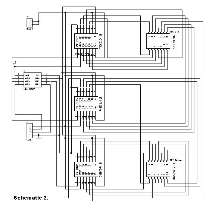
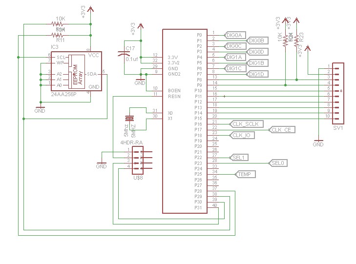
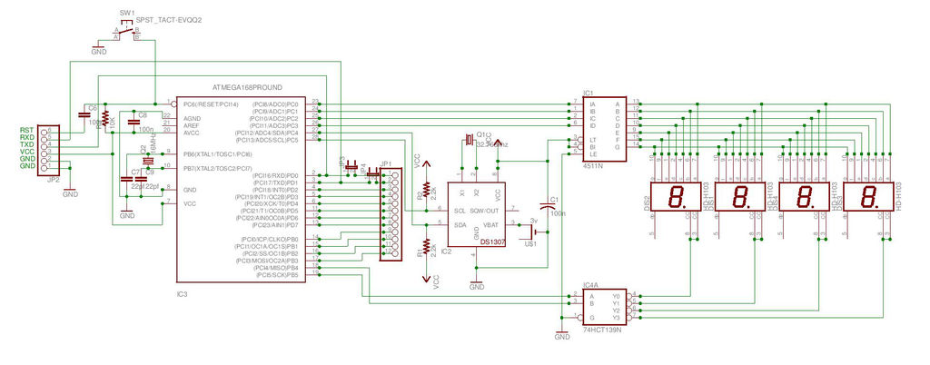
The clock design presented here only decodes the time data and daylight savings correction data. The software could easily be modified to include decoding of the other information bits, if desired. The the low frequency WWVB signal strength is weak and reception can be problematic. Signal acquisition time is variable, depending on location and atmospheric conditions. Reception is usually best at night between 8pm - 4am. To use the clock, just apply power and wait for reception of the WWVB signal. When the clock receives a complete error-free frame of data, it will automatically reset the display to show the correct time. After the initial time correction, the clock will maintain time even if WWVB reception is lost. As shown in the schematic (pdf format), the heart of the clock is a PIC 16F628 microcontroller running at 4 MHz. Decoded time data is sequentially output from the microcontroller (RA0 - RA3) to the 7-segment decoder/drivers on a 4-bit data bus.
The data is output sequentially as seconds, 10s of seconds, minutes, 10s of minutes, hours, and 10s of hours. The microcontroller outputs (RB1, RB2, RB3) route a 10 uSec stroble pulse from RB4 out to each of the 7-segment decoder/drivers at the proper time to latch the data bus values.
Seconds and 10s of seconds display values are updated once per second. Minutes, 10s of minutes, hours, and 10s of hours are updated once per minute. The display consists of 1" red-orange LED 7-segment displays. The decimal points on the displays are used to form colons to separate the seconds, minutes, and hours. The 10s of seconds and 10s of minutes displays are mounted upside down to form the upper colon dots. The WWVB receiver is a C-MAX model CMMR-6 and is available from Digi-Key (www.digikey.com) as part # 561-1014-ND complete with loopstick antenna.
Data output from the receiver is sampled by the microcontroller on RB0. Construction I have built two of these clocks, one using point-to-point wiring and one using a pcb. Both versions perform well. Just keep the receiver away from noise sources and the wire / trace lengths short to minimize inductance.
I found that the receiver is also sensitive to magnetic fields produced by power supplies. I used a 9V, 200 mA "wall-wart" instead of an internal power supply to eliminate this problem. My pcb was designed using Free PCB software www.freepcb.com. The artwork contains both the main board and the display board on a single layout to save the cost of two separate boards. I purchased the pcb from www.4pcb.com by sending them the gerber files and using their "bare-bones" process.
The "bare-bones" process does not include solder mask nor silk-screen. Just cut off the display board from the main board and mount it at a right angle to the main board and wire them together using the pads provided. Receives time broadcast from WWVB, Fort Collins, CO Auto synchronizes internal time with WWVB time Maintains local time when WWVB signal is lost This version is for Pacific Standard Time, and auto detects/corrects for Daylignt Savings Time 6-digit display of hours, minutes, seconds using 1" seven-segment LED displays WWVB sync indicator Time display is in 12-hour format PIC 16F628 microcontroller Software written in C All tools (schematic editor, C compiler, PCB layout software, PIC programmer are free and available for download on the web.
🔗 External reference
Related Circuits
Communication with the MCP3028 ADC chip is achieved through a straightforward serial interface that adheres to the SPI protocol. The PIC16F84 or PIC16F628 does not possess a hardware SPI peripheral. However, a software-implemented SPI protocol can facilitate communication with...
After constructing numerous Nixie Tube Clocks based on online designs, a personal design was developed. This clock utilizes IN-12 Nixie Tubes and an 8-core Propeller Microcontroller. Although the Propeller may be more powerful than necessary for this task, it...
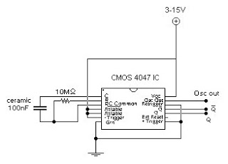
This circuit generates a digital square wave that can be displayed directly or utilized to drive additional circuits. It employs the CMOS 4047 Low-Power Monostable/Astable Multivibrator, as referenced in Tom Duncan's "Adventures with Digital Electronics" book, to control a...
This 6" x 18" clock requires 52 light sources and aims to enable individuals to read the time without glasses. For 25 years, the search for sufficiently large clocks that could be seen without glasses proved fruitless, leading to...
This precise one-pulse-per-second clock is constructed using a few common components and is powered by a 50 or 60 Hertz mains supply without any direct connection to it. A beep or metronome-like click, along with a visible flash, indicates...
This is the second instructable focused on creating a digital watch as a learning experience. An Atmega644 chip from a Sanguino was available, which would have sufficed, but the intention was to burn an Arduino bootloader and test its...