
Arduino SFR Ranger Reader

The Devantech SRFxx ultrasonic range finder operates effectively in various applications, particularly in distance measurement and obstacle detection. The integration of the I2C protocol allows for a compact and efficient communication method, ideal for projects requiring multiple sensors. The use of the Arduino's Wire Library simplifies the coding process, allowing for straightforward implementation of the I2C communication.
To set up the circuit, begin by establishing power connections. The SRFxx should be powered by a stable 5V source, with the addition of a 100µF capacitor placed in parallel to filter out any voltage spikes or noise that may affect sensor performance. This capacitor serves to smooth the power supply, ensuring reliable operation during measurements.
Next, connect the SDA and SCL pins of the SRFxx to the specified analog pins on the Arduino. This connection enables the Arduino to communicate with the sensor using the I2C bus. It is crucial to maintain proper wiring to prevent communication errors. The SDA line carries data, while the SCL line provides the clock signal, synchronizing data transmission between the devices.
In scenarios where multiple SRFxx units are utilized, each device must be assigned a unique address to avoid conflicts on the I2C bus. This can typically be achieved by following the manufacturer’s guidelines for re-addressing the devices, ensuring that each unit can be individually addressed by the Arduino.
The Arduino sketch will handle the initialization of the Wire Library, set the appropriate I2C addresses, and manage the reading of distance measurements from the SRFxx. Proper error handling and data validation should be implemented to ensure accurate readings and robust performance in various environmental conditions. The versatility of the I2C protocol and the SRFxx range finder makes this combination suitable for a wide range of robotics and automation projects.This example shows how to read a Devantech SRFxx, an ultra-sonic range finder which communicates via the I2C synchronous serial protocol, using Arduino`s Wire Library. The I2C protocol involves using two wires to send and receive data: a serial clock pin (SCL) that the Arduino pulses at a regular interval, and a serial data pin (SDA) over which
data is sent between the two devices. As the clock pulse changes from low to high (known as the rising edge of the clock), a bit of information containing the address of a specific device and a request for data, is transferred from the Arduino to the I2C devices over the SDA line. When the clock pin changes from high to low (the falling edge of the clock), the called upon device transmits it`s data back to the Arduino over the same line.
Because the 12C protocol allows for each enabled device to have it`s own unique address, and as both master and slave devices to take turns communicating over a single line, it is possible for your Arduino to communicate with many devices (in turn) while using just two pins of your microcontroller. Attach the SDA pin of your SRFxx to analog pin 4 of your Arduino, and the SCL pin to analog pin 5. Power your SRFxx from 5V, with the addition of a 100uf capacitor in parallel with the range finder to smooth it`s power supply.
If using two SRFxxs on the same line, you must ensure that they do not share the same address. Instructions for re-addressing the range finders can be found at the bottom of the code below. 🔗 External reference
Related Circuits
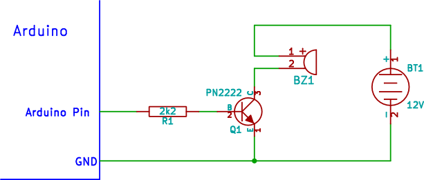
Connecting a buzzer to an Arduino when the buzzer operates at a different voltage than the Arduino involves using an NPN transistor to interface between the two. To implement this circuit, the following components are required: an Arduino board, a...
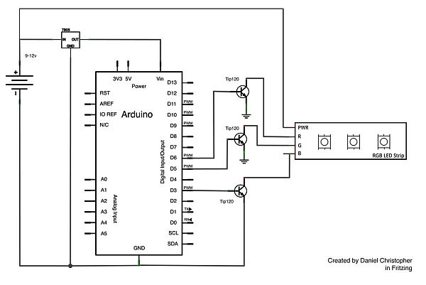
This document outlines the assembly of a circuit designed to pulse width modulate (PWM) a high-power RGB LED strip and program an Arduino to cycle through various colors. The term "high power" refers to a voltage range of 9-12...

The Arduino is a user-friendly and versatile controller platform suitable for various projects. Recently, an Ethernet shield was purchased for the Arduino to enable remote control of projects, which proved to be highly effective. This led to the idea...
Part fill valves are commonly utilized in rainwater tanks. The valve activates when the water level in the tank drops to a low position. Part fill valves play a crucial role in the management of water levels in rainwater harvesting...
Software on a MacBook Pro includes Laidman & Katsura's WaveWindow, which functions as a software oscilloscope. It is beneficial for individuals working with sound on the Mac, offering an educational and entertaining experience. Additionally, Faberacoustical's Signal Scope allows for...
This project is an Arduino-based light control system that is ideal for beginners. It allows the fading of colors or lights by detecting hand movements nearby. The system transitions from a purple-blue hue to a fiery red-orange. The assembly...