
Arduino FM radio receiver shield
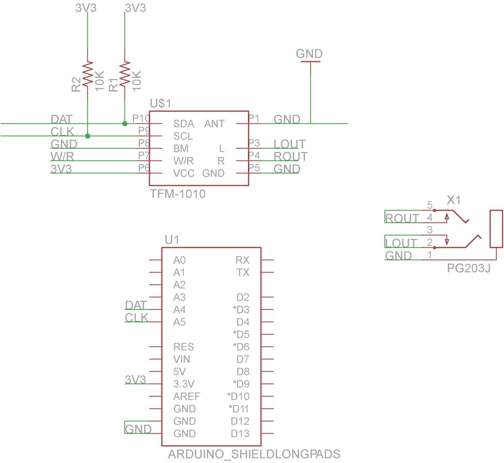
The FM radio receiver shield is designed to interface seamlessly with an Arduino board, allowing for versatile applications in audio projects. The AR1010 radio chip is a highly integrated solution that simplifies the process of receiving FM signals. The circuit layout should include the necessary connections for power, ground, and signal output to the Arduino's analog or digital pins, depending on the implementation.
The fabrication process begins with the design phase in Eagle, where the circuit schematic and PCB layout are created. It is essential to ensure that the design adheres to the specifications for laser cutting, particularly the trace width and the use of a single-sided PCB. The exported PNG file must maintain the correct dimensions and clarity to facilitate accurate cutting.
During the laser cutting process, the settings must be carefully adjusted based on the material used for the PCB and the capabilities of the laser cutter. The Marble setting is typically effective for etching away spray paint from the copper surface, revealing the copper traces beneath. After the etching process, the PCB can be cleaned and prepared for soldering components, including the AR1010 chip, capacitors, resistors, and connectors.
Once the components are soldered onto the PCB, the shield can be attached to the Arduino board. Programming the Arduino with the provided code will enable the FM receiver to function correctly, allowing users to tune into various FM stations. This project not only serves as a practical application of electronics and programming but also provides a hands-on experience in PCB design and fabrication.This Instructable will show you how to build your own FM radio receiver shield to be used with an Arduino board. The radio chip we are going to be using is the AR1010 on a breakoutboard found at Sparkfun or Electrokit and there will be code to get you up and running provided later on.
We are going to use an laser cutter for the shield fabrication. F irst we build up our circuit using eagle. There are many Instructables out there on how to do it such as this or this. You can download my eagle files I have been using when building this board below. Things to consider is that when you are going to be using the laser cutter for doing pcbs you have to remeber that it is one sided pcbs that is be far easiest and also that the traces has to be 15 mil or wider otherwise the laser and etching process might etch them away. Once you have your layout done it is time to export it to a more laser friendly format. The first picture below is the finished pcb layout and the second is the schematic of the circuit. To get the nice monochrome laser friendly picture (pic 3 below) you have to export it from eagle as png.
1. Select the layers that you are interest in laser cutting. I tend to only select the top layer and the pads since there residesnearlyalways all thenecessaryinformation. Next thing to do is to prepare the copper pcb. This can be found in many sizes and the one I have hear is 160x100x1, 6 mm and is pretty standard her in Sweden.
Put the exported file into yourfavoritelaser program, in this case Illustrator, and make sure that the size is correct and everything is looking fine. After that it is time to send it to the laser. The settings I use to etch the spraypaint away is the Marble setting on my Epilog 40 w laser. This will change depending on your laser type. 🔗 External reference
Related Circuits
This web page is a memorial to Mike Caughran, KL7R, who passed away unexpectedly in January 2007. Mike was an enthusiastic experimenter, well-regarded in the homebrew radio electronics community. He is best known as the co-creator and collaborator with...
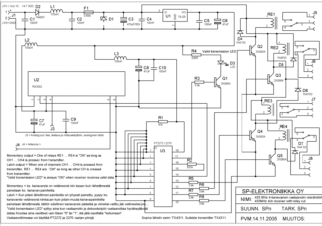
Momentary output: One of the relays RE1...RE4 is ON as long as CH1---CH4 is pressed from transmitter. Latch output: when one of channels CH1...CH4 is pressed from transmitter RE1...RE4 are ON as long as other CH is pressed from...
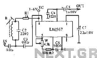
This figure illustrates the schematic of the LM567 SCA broadcast reception information machine. The LM567 serves as a narrow-band phase-locked loop designed primarily for SCA broadcast demodulation. The configuration includes a potentiometer (W) and capacitor (C6) that determine the...
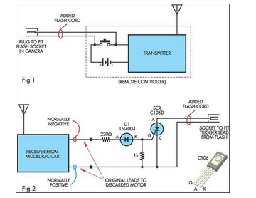
A radio-controlled electronic flash is an essential tool in any photographer's kit. Professionals frequently utilize them, such as wedding photographers. A radio-controlled electronic flash system typically consists of a transmitter and one or more receivers. The transmitter, often mounted on the...

The individual was not inclined to create and program the timing controller for the PCB laser printer. They recalled having a laser tag gun that had been misaligned during a previous disassembly. The device in question is a Nerf...
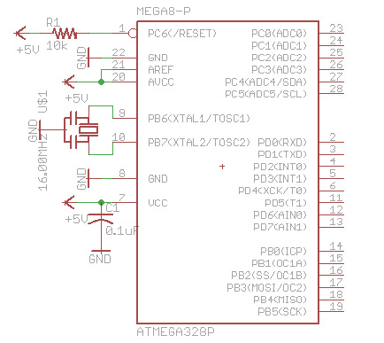
There are many bare-bones Arduinos available on the internet. Most of them are assembled on a solderless breadboard and utilize an ATmega168 (or ATmega328) microcontroller with an Arduino bootloader, a resonator (which may have built-in capacitors or require two...