
small bare bone arduino bluduino
The bare-bones Arduino is a minimalistic version of the standard Arduino boards, designed for users who need a compact, cost-effective solution for their projects. The schematic typically includes the following essential components:
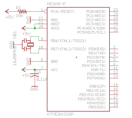
1. **Microcontroller**: The core of the circuit is the ATmega168 or ATmega328 microcontroller. This device is responsible for executing the program code and controlling the entire system. It features a range of digital input/output pins, analog inputs, and communication interfaces, making it versatile for various applications.
2. **Bootloader**: The Arduino bootloader is pre-installed on the microcontroller, allowing users to upload code directly via a serial interface without needing an external programmer. This feature simplifies the programming process and enables rapid prototyping.
3. **Resonator**: A resonator (or crystal oscillator) is included to provide a stable clock signal for the microcontroller. This component is crucial for ensuring accurate timing and reliable operation of the microcontroller. Depending on the design, it may include built-in capacitors or require the addition of two external capacitors to function correctly.
4. **Resistor**: A pull-up or pull-down resistor may be included in the circuit to ensure that the microcontroller's input pins are at a defined logic level when not actively driven. This is important for preventing floating inputs, which can lead to unpredictable behavior.
5. **Power Supply**: The schematic will also indicate how the circuit is powered, which typically involves connecting to a USB power source or a battery. Voltage regulation may be necessary if the supply voltage exceeds the acceptable range for the microcontroller.
6. **Breadboard Layout**: The use of a solderless breadboard allows for easy assembly and modification of the circuit. This flexibility is particularly beneficial for prototyping and testing different configurations without the need for soldering.
The bare-bones Arduino design is particularly advantageous for applications where space and cost are critical factors, such as in embedded systems or DIY electronics projects. By focusing on essential components and omitting unnecessary features, this design allows users to create custom solutions tailored to their specific needs.There are many `bare bone` Arduinos you can find from internet. Most of them are on a solderless breadboard with a ATmega168 (or 328) chip with Arduino bootloader, a resonator (with built-in capacitors or needs 2 capacitors), a resistor.Here is a quick drawn Eagle schematic diagram. This is truely `bare bone` Arduino which means that.. 🔗 External reference
Related Circuits
This is a simple yet reliable device based on one of the oldest integrated voltage regulators, the LM723. The LM723 is a versatile voltage regulator that can be configured to provide a wide range of output voltages. It is capable...
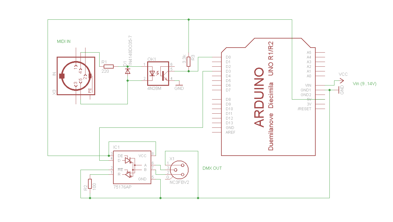
A simple Arduino MIDI-to-DMX control was created for a robot band named Science Fiction Children. The setup consists of two inexpensive LED Par56 lights from Stairville, a basic DMX dimmer pack, and Ableton Live for sound management. The objective...
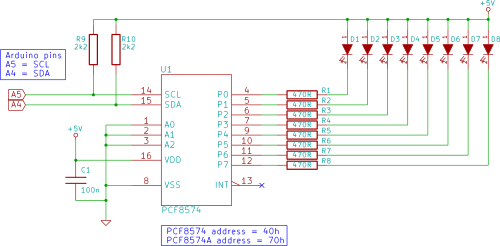
Connect eight LEDs to an Arduino and create a Knight Rider display using only two Arduino pins in this tutorial. This is achieved by utilizing a PCF8574 I/O expander IC. To implement the Knight Rider display using an Arduino and...
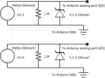
The piezo element is connected solely to Channel 1 (Arduino A[0] port). Channels 1 through 6 are linked to female mono jacks, with the ground (GND) wiring arranged in series from jacks 1, 2, and 3, continuing to the...
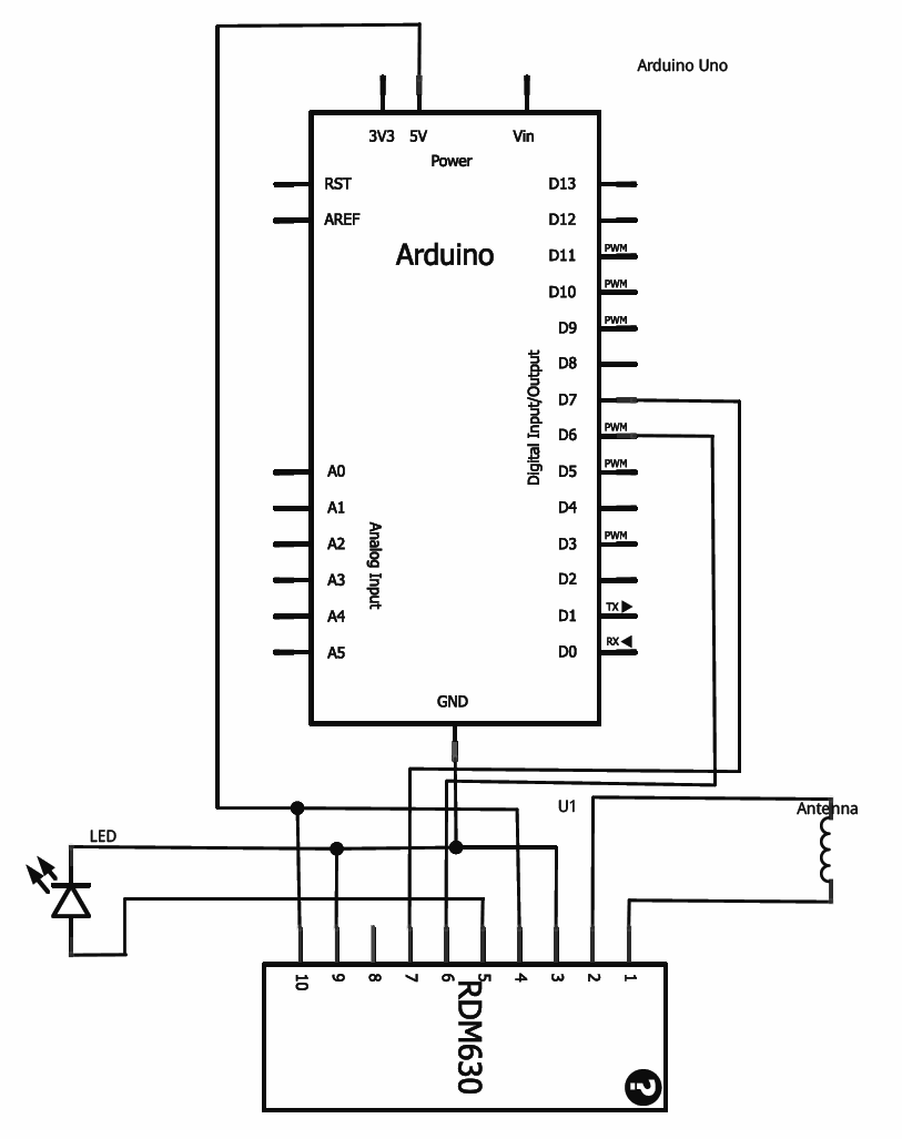
This tutorial provides guidance on integrating RFID functionality into a project using the RDM630 module from Seeed Studio, specifically its UART version. The module is mounted on a compact board with pre-soldered connectors, making it compatible with breadboards. To...

The initial intention was to purchase a Nebulophone; however, the price exceeded the budget. It was discovered that programming an AtMega 328 using ArduinoISP was a feasible alternative. If the code was compatible with Arduino, it was logical to...