
SCA broadcast receiver circuit diagram
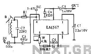
The LM567 SCA broadcast reception circuit is an efficient solution for demodulating SCA signals, utilizing the phase-locked loop (PLL) architecture to achieve a stable output. The LM567 integrates various functionalities, including a voltage-controlled oscillator (VCO) that can be adjusted to lock onto the desired frequency. The phase-locked loop works by comparing the phase of the input signal with that of the VCO, adjusting the frequency of the VCO until the two are in sync.
The choice of components is critical for the performance of the circuit. The potentiometer (W) allows for precise adjustments to the VCO frequency, accommodating variations in the input signal and ensuring optimal demodulation of the SCA broadcast. The capacitor (C6) plays a vital role in the stability and response time of the VCO, influencing the overall bandwidth of the demodulation process.
The inductance coil (B) is specifically designed to provide the required inductance value, which, in conjunction with the selected resonant capacitor, forms a tuned circuit that enhances signal reception. The 2200pF ceramic capacitor is chosen for its low equivalent series resistance (ESR) and stability over a range of temperatures, making it suitable for RF applications.
In summary, the LM567 SCA broadcast reception circuit is a well-structured design that leverages a combination of precise tuning elements and high-quality passive components to achieve effective demodulation of SCA signals, ensuring reliable performance in various broadcasting scenarios.This figure is converted into the manifold LM567 SCA broadcast reception information machine schematic. LM567 narrow-band phase-locked loop center to meet the basic role of SCA broadcast demodulation. R2 LM567 5,6,7 feet between the potentiometer W, C6 determine the IC internal VCO center frequency, the center frequency can be locked trimmer potentiometer W to adjust. Inductance coil B 0.088 enameled high strength available in 10X10 (mm) IF-shaped core transformer 360 laps around the inductance of 3mH, select the resonant capacitor 2200pF ceramic capacitor, W can be used to fine-tune the resistance, no special requirements other components.
Related Circuits
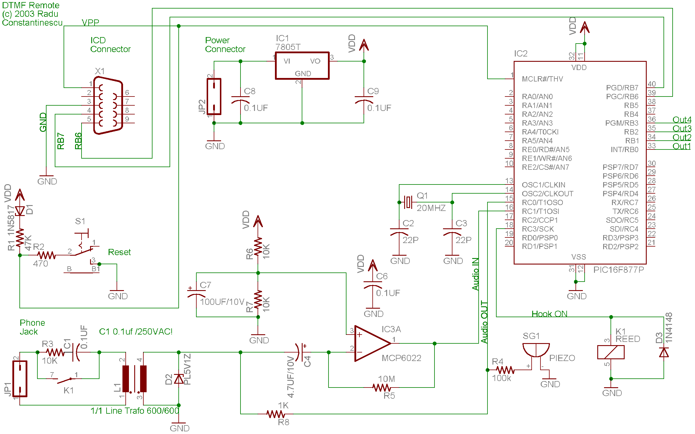
A telephone remote control system allows users to perform various functions remotely using their phone. This system automates complex tasks, simplifying the development and operation of telephone systems. The telephone remote control system is designed to enhance user interaction with...
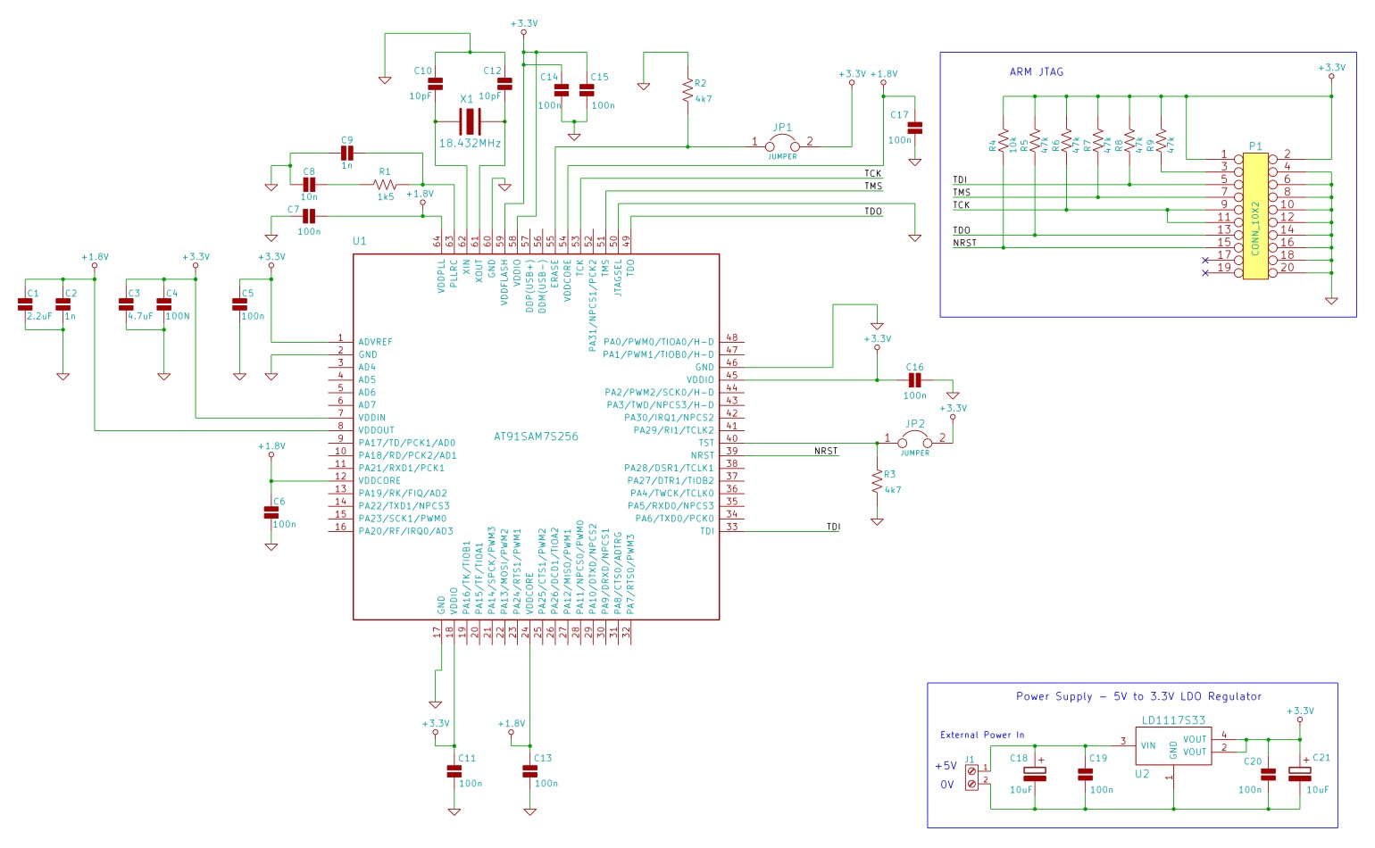
The minimum number of supporting components required to build a circuit using AT91SAM7S microcontrollers. This example uses the AT91SAM7S256 ARM7 microcontroller. To construct a circuit utilizing the AT91SAM7S256 ARM7 microcontroller, a minimal set of supporting components is essential to ensure...
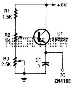
This regulator can be used with a +6-V source to supply the ZN416E low-voltage TRF radio receiver IC with the necessary +1.5 V. R3 sets the output voltage. The circuit utilizes a voltage regulator designed to convert a +6 V...
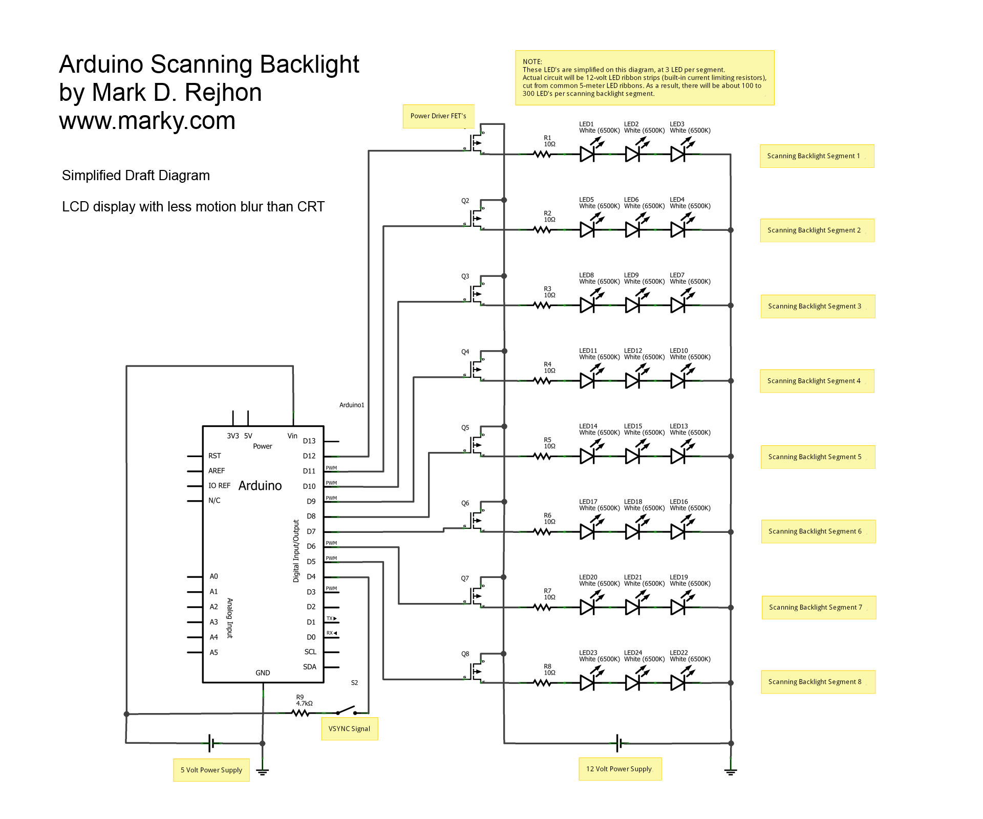
This is a simplified schematic diagram for a homemade scanning backlight driven by an Arduino, an open-source electronics prototyping platform. The Arduino monitors the VSYNC signal (input-lag compensated) and executes a backlight scanning sequence, using ultra-short strobes of super...
This circuitry provides a magnification of 1,200,000 times, with a bandwidth ranging from 0.5 to 14 MHz. The input impedance is 700 ohms, while the output impedance is 35 ohms when measured at 5 MHz. The output noise level...
This is a fire alarm system utilizing the IC TD2002 suite to detect fire incidents. The alarm is crucial in residential complexes, allowing for early detection. It operates by detecting fog generated by fire, which reduces the light reaching...
Warning: include(partials/cookie-banner.php): Failed to open stream: Permission denied in /var/www/html/nextgr/view-circuit.php on line 713
Warning: include(): Failed opening 'partials/cookie-banner.php' for inclusion (include_path='.:/usr/share/php') in /var/www/html/nextgr/view-circuit.php on line 713